Testing 10 Gigabit Ethernet
Guylain Barlow, Innocor Ltd.
gbarlow@innocor.com
www.innocor.com
The growing presence of the IP protocol at the heart of telecom networks is putting pressure on vendors and service providers to optimize the way user traffic is managed. One resulting change is to extend the reach of the long-established LAN-based Ethernet protocols into the core of networks. This spawned the creation of Gigabit Ethernet and more recently 10 Gigabit Ethernet (10GbE) as defined by the IEEE in its 802.3ae specification. Vendors and service providers are now seeking independent sources to verify their 10 Gigabit Ethernet products. The main challenge for test equipment manufacturers consists of determining the appropriate set of features to meet the needs of the 10GbE user. This article examines key 10GbE applications and the resulting test requirements.
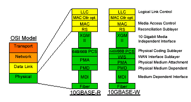
From a network point of view, the chief purpose of 10GbE is to carry IP traffic. Consequently, the 10GbE test functions related to switching and routing are similar to those on more mature protocols such as POS (Packet over SONET/SDH) and lower speed Ethernet. This includes the evaluation of parameters such as latency, frame loss, and the generation of IP and upper layer traffic. On a different front, the seamless nature of 10GbE, as Ethernet carries data from LAN to WAN, fuels the need to integrate 10GbE as a transport mechanism. This results in the implementation of 10GbE interfaces onto transport equipment, which generates a different set of test requirements. More specifically, 10GbE is found in two main versions, namely 10GbE LAN (10GBase-R) and 10GbE WAN (10GBase-W) where, in the latter case, SONET/SDH forms the underlying transport mechanism. Consequently, 10GbE may be carried across long haul and metro areas using equipment that collects 10GbE LAN links for transport over SONET/SDH in the form of 10GbE WAN. Transport users will therefore focus on the testing of framing, line encoding, and the integration of 10GbE LAN/WAN. Two generic 10GbE applications have so far been described in the form of upper layer application testing and transport. Another significant function arises in the development of 10GbE as components, such as modulating devices and framers, require specific characterization. In this case, the main interest is to measure the optical properties of signals, verify the timing, and test the low level encoding of the information. In addition, testing 10GbE in the field can be added to this list although this mainly becomes a matter of portability. The IEEE 802.3ae standard is the starting point to determine the specific elements of 10 Gigabit Ethernet that require testing. As illustrated in Figure 1, 10GbE is composed of a number of sublayers. Of particular interest are the WIS (WAN Interface Sublayer) that represents the SONET/SDH portion of 10GBase-W, the PCS layer (Physical Coding Sublayer), and the MAC (Media Access Control) layer. It is important to note that 10GbE WAN (9.953Gbits/sec) and 10GbE LAN (10.3Gbits/sec) use different line transmission rates. The PCS comprises the functions of scrambling and encoding where each 64 bits of information are preceded by 2 synchronization bits. The MAC layer is virtually the same as for other Ethernet rates where upper layer information is encapsulated with a MAC header. MAC Frames are separated by idle bytes in the form of IFGs (Inter-Frame Gap), generally inserted at the RS (Reconciliation Sublayer).

Figure 1 10 Gigabit Ethernet Model
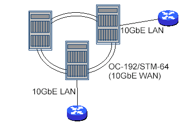
Here is a deeper look at 10GbE on transport equipment for which an example is shown in Figure 2. An important test device consideration is a unified, software switchable platform that provides 10GbE WAN and 10GbE LAN. In addition, support for lasers at different wavelengths and reaches based on MSA (Multi Source Agreement) technology provides flexibility. At least four 10Gbits/sec MSA technologies exist on the market including XENPAK, its evolution to XPAK, XFP, and 300-pin MSA. The first two technologies use a XAUI electrical interface to connect into a 10GbE device. While these interfaces are suitable for most equipment, they do not provide control over the PCS layer as the XAUI interface sits at the XGMII level as in Figure 1. For most transport users, the XFP or 300-pin MSA technologies are therefore preferable. XFP is an emerging technology not generally available at the time of this article. In addition, there will be optical power limitations especially at 1550nm. The 300-pin MSA technology satisfies transport test requirements; however, its main limitation is the fact that it is hot pluggable. Another aspect the transport user may consider are very long haul applications that use digital wrapping and FEC (Forward Error Correction) techniques to extend signal reach. The emerging standard for this function is based on ITU-T G.709 that operates at 10.7Gbits/sec for OC-192/STM-64. A similar standard that supports 10GbE LAN long distance transport, will likely arise since current implementations are proprietary and difficult to test independently.

Figure 2 Transport Equipment Sample Configuration
The following provides a comprehensive test feature list that as applicable to 10GbE interfaces on transport equipment.
Payload Test Patterns: robust PRBS (Pseudo Random Bit Sequence) test patterns provide bit level accuracy. These patterns are preferable to straightforward CRC validation, which provide frame level error detection.
PCS coding layer: the test equipment should ideally detect block errors, report rates and be able to inject such errors. In addition, the test equipment should control sync header bits to inject and detect High BER (Bit Error Rate) and Loss of Lock alarms.
Faults: Remote Faults and Local Faults ordered sets provide fault detection mechanism.
Detection and injection are of interest to the transport user.
MAC Layer Errors: capabilities to fully exercise MAC include CRC controlled error injection and monitoring. Frames of multiple sizes shall also be provided including undersized, jumbo and oversized. Support for Ethernet Type II and 802.3 shall be provided along with VLAN.
Bandwidth Control: this refers to tight control over Inter Frame Gap (IFG) sizes including IFGs below the allowable limits.
Flow control features: this ensures matching traffic rates between the LAN (10.3Gbps) and WAN (9.953Gbps) interfaces. This is accomplished via MAC pause frames or ifsStretch capabilities.
WIS layer testing: this is the same as testing SONET/SDH. This includes B1, B2, B3 error rates, SONET/SDH alarms, and overhead bytes.
Disruption Time Measurements: in the event of protection switching, the response offered by the network equipment should be measurable.
Clock synchronization: this includes the options to provide internal clock timing, line timing, and clock rate variations of up to +/-100ppm for 10GbE LAN.
The upper layer applications supported by routing, switching, and even storage devices generate different test needs. Two main categories of test can be defined in the form of data plane and control plane testing. Data plane requirements, especially in the case of 10Gbps rates generally involve a large number of dedicated hardware resources.
Conversely, control plane testing involves significant software based features. Here are sample requirements for upper layer testing.
Protocol support: this includes protocols such as IPv4, IPv6, TCP, UDP, IGMP, ARP, and involves the edition of header and payload fields.
Traffic streaming: refers to the generation of multiple traffic streams, each with its own protocol and bandwidth definitions. This includes the support of multiple MAC and IP addresses to emulate traffic from multiple sources and destinations.
Quality of Service: includes the evaluation of latency and packet jitter based on injected timestamps. In addition, sequence numbering will identify out-of-sequence packets and packet loss.
Filtering: allows for the reporting of statistics based on groups of packets. Buffer captures: empower users to capture packets and save them for later retrieval. Protocol decodes may also be performed on the captured data.
Control plane testing refers to the conformance to standards and the performance testing of routing protocols. Examples include the testing of OSPF, BGP, and MPLS specific protocols such as LDP, CR-LDP, and RSVP-TE.
One the 10GbE component testing front, the requirements to test framing devices center around detailed PCS and MAC features and potentially an electrical interface although optical to electrical conversion may be performed. On the modulating device front, such as transponders, test functions include: evaluation of OSNR (Optical Signal to Noise Ratio), stressed eye testing accomplished by adding noise to the optical signal, jitter tolerance generation and measurements, and receiver sensitivity. These tests generally involve a dedicated hardware test platform and the generation of 802.3ae test patterns such as square wave, mixed patterns, and PRBS31. The main reason is the specificity of these tests.
The broad spectrum of test requirements listed above puts pressure on test equipment manufacturers to address the largest market possible. In many cases, test requirements stretch the hardware capabilities of the equipment and this poses technical challenges. It remains that 10GbE test devices are designed to address specific target markets and applications. Innocor's designed its TestpointTM Tsunami shelf platform and the SM- 9953EX single-slot system to support test applications for the 10GbE transport market, the upper layer manufacturing space, and to cover low level functions for the framer component market. In addition, Innocor's products test a range of functions from SONET/SDH, G.709, Gigabit Ethernet, ATM, POS while integrating functions such as optical switching devices. Innocor offers low cost, robust platforms and a high level of integration.
For more information about Innocor's tester and IP core solutions, visit the Innocor web site at www.innocor.com or e-mail info@innocor.com.
Related Articles
- Can 10 Gbps Ethernet be an Embedded Design Solution?
- Can 10 Gbps Ethernet be an Embedded Design Solution?
- Verify timing of parallel PHY interfaces for Gigabit Ethernet
- Integrating a PCI Express Digital IP Core into a Gigabit Ethernet Controller
- Testable SoCs : How systems level considerations impact cost-effective Gigabit Ethernet PHYs
New Articles
- System level on-chip monitoring and analytics with Tessent Embedded Analytics
- What tamper detection IP brings to SoC designs
- RISC-V in 2025: Progress, Challenges,and What's Next for Automotive & OpenHardware
- Understanding MACsec and Its Integration
- Discover new Tessent UltraSight-V from Siemens EDA, and accelerate your RISC-V development.
Most Popular
|
|
E-mail This Article |
|
Printer-Friendly Page |


