AMBA Parameter Configurable Multi-Channel DMA Controller (typically 1 to 256)
MIPI I3C Basic Secondary Controller
As a secondary controller, the I3C-SC can act either as a bus target or a bus controller. Compliant to the I3C Basic specification, the core communicates in Single Data Rate (SDR) mode but can tolerate High Data Rate (HDR) traffic. It can coexist and communicate with legacy I2C devices, and it can optionally be configured to operate as such in an I3C or I2C bus
CAST is a MIPI Alliance member
When acting as a target, the I3C-SC needs no firmware support to parse and execute the broadcast or direct Common Command Codes (CCCs) relevant to I3C Basic targets. It can be assigned a Dynamic Address by the bus controller or use its legacy I2C static address, it supports Hot-Join and can generate In-Band Interrupts when directed by the host to do so. When the I3C-SC core is the only bus controller, then Hot-Join is not possible, and static addressing should be used.
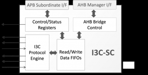
Designed for easy integration, the I3C-SC can operate in two different modes. Under normal mode, data from private I3C or legacy I2C write transfers are stored to a FIFO and made available to the host via an APB Subordinate interface. In a similar way, the host provides data to be used for private I3C or legacy I2C read transfers via the core’s APB subordinate interface. Alternatively, the core can operate in I3C-to-AHB bridging mode, where it autonomously converts private I3C or legacy I2C transfers to accesses on its AHB manager port using a simple yet configurable over-I3C protocol. Under the I3C-to-AHB bridging mode, the core acts as a an I3C bus target, needs no software assistance, and provides the I3C bus controller access to the local AHB bus, enabling remote monitoring, configuration, debug, or data exchange. The selection between normal and bridging operation modes is under software control via the core’s control register.
The highly flexible core offers synthesis-time and run-time configuration options, which allow adapting its size and behavior to the application requirements. For example, the AHB-manager interface and the clock domains synchronizers can be removed at synthesis to reduce the core’s silicon footprint. During run-time, the I3C private data and I2C traffic can be bridged to the core’s AHB-manager interface or transferred to and from the host via the core’s APB subordinate interface. Also, parameters defining the CCCs processing (e.g. own-static-address, provisional ID), the over-I3C protocol (e.g. number address bytes, max number of data bytes) and the AHB-manager port behavior (e.g., AHB burst type & address wrapping) are all run-time configurable via the core’s registers.
The I3C-SC core adheres to the industry’s best coding and verification practices to ensure trouble-free implementation in ASIC or FPGA technologies. Technology mapping, constraining, and scan insertion are straightforward, as the core contains no multicycle or false paths and uses only rising-edge-triggered D-type flip-flops, no tri-states, an asynchronous reset line per clock domain, and clean clock domain crossing modules. Its reliability and low risk have been proven through rigorous verification and FPGA validation.
View MIPI I3C Basic Secondary Controller full description to...
- see the entire MIPI I3C Basic Secondary Controller datasheet
- get in contact with MIPI I3C Basic Secondary Controller Supplier
Block Diagram of the MIPI I3C Basic Secondary Controller


