By Swapnil Sapre, Mindtree
ABSTRACT
This document discusses Random constraint-based verification and explains how random verification can complement the directed verification for the generic designs. In our case this is demonstrated by an “ARM processor based platformâ€.
The Constrained Random Techniques (CRT) can be effectively used for verifying large complex designs. As CRT can automatically generate a large number of test cases, it can hit corner cases faster and help in reaching conditions that would normally not be easily reached with traditional methods. These features are built over and above an already existing legacy Verilog environment.
Random verification for generic designs is implemented by Transaction based Models or Bus Functional Models. The language used for the Verification environment is SystemVerilog.
1.0 Introduction
“Reuse†is a term that is frequently associated with verification productivity. When faced with writing a verification environment from scratch, or modifying an existing one, the choice will often be to stick with what’s familiar and already in existence.
“Methodology†lays a foundation for a robust verification environment which is capable of handling complex verification needs and speed up the verification process.
When a verification environment is needed for a new design, or for a design revision with significant changes, it is important to objectively look at the shortcomings of the existing verification environment and expected productivity gain with the new methodology and determine the best solution.
In our case we need to find an optimum balance between re-usability of our legacy Verilog environment and the resource utilization along with limited timelines in adopting the new methodology. This can be accomplished by reusing the knowledge /legacy code from an earlier project along with an upgrade to a new methodology provided with the verification language, that is SystemVerilog.
There are already few verification methodologies available from Synopsys like VMM/RVM which helps in building a robust verification flow. But keeping in our limited resources and stringent timelines, we focused on implementing a simpler flow based on Constraint Random Techniques (CRT), which helps in generating the interested test scenarios automatically. This is an in-built feature available with SystemVerilog.
This document demonstrates the introduction of Constraint Random Verification with SystemVerilog while re-using the legacy Verilog verification environment (keeping what we knew best).
2.0 Design Under Test
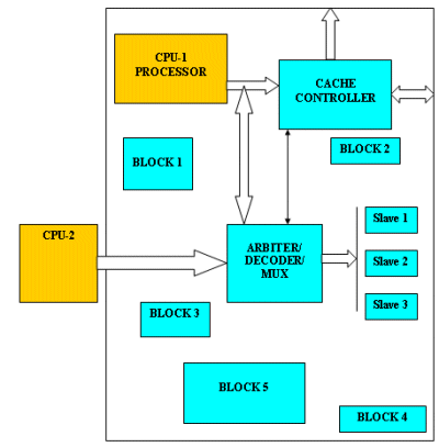
The Figure-1 below shows the top level view of our design under test. This was an ARM 1136 processor based platform, consists of different peripherals which are closely connected to the ARM processor through AHB interface and provides a control and communication link with the other sub-units on the SOC. The Testbench for the same was in Verilog. The block level directed testing was done and assertions were present for the bus interface monitoring and specification violations.

Figure-1: Block Diagram of DUT
3.0 Directed Verification of DUT-Legacy/existing environment
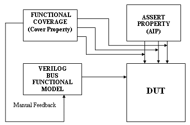
Figure-2 below shows the legacy Verilog based verification environment which was earlier used to verify the functionality of the platform.

Figure-2: Legacy BFM based Verification Environment
The legacy verification suite of scenarios consisted of a group of ARM based assembly patterns and Verilog based BFM scenarios.
The assembly patterns were targeted for the integration check between 2 or more sub modules and were also based on the application specific scenarios within and for the platform.
The BFM based Verilog patterns were verifying the integration and other checks which were not possible through assembly patterns. The BFM in Verilog was replacing the ARM processor and was generating the manually requested transactions.
This traditional approach of verifying the designs by writing the Verilog/VHDL testbench leads the designers to completely rely on developing a directed environment and hand-written directed test cases. These directed tests provide explicit stimulus to the design inputs, run the design in simulation, and check the behavior of the design against expected results. This approach may provide adequate results for small, simple designs but it is still a manual and somewhat error-prone method. In addition, directed tests were not able to catch obscure defects due to features that nobody thought of. Moreover these traditional methods have very limited and cumbersome random capability
With increase in complexity and size of design, there is higher and higher demand on exhaustive functional verification. These demands are necessitating the development of new verification technologies, such as, constrained random verification, score-boarding and functional coverage, to achieve exhaustive functional verification goal.
These development methods for reusable verification environment are much easier and helpful in constraining verification to find out the corner cases and hidden bugs which are left undetected with conventional directed approach.
4.0 Constraint Random based Verification
Now before starting the implementation of a Constraint Random Verification environment, there were few points of consideration.
Language
System Verilog was the first choice to be used since it is an IEEE standard as well as easy to learn, for those who are already familiar with Verilog. It provides some additional constructs for the randomization implementation and Object Oriented techniques for improving the Verification environment.
Tool
The quest began for the tool (simulator), that is compatible and can support maximum number of constructs and features of System Verilog. We had a few options and found that synopsys-vcs-/vY-2006.06 was much ahead of its counterpart cadence-ius-5.7.
Approach
1. VMM (ARM & Synopsys -Verification Methodology Manual Based)
VMM is believed to be the most efficient method, for doing the testbench design from scratch. It provides plenty of inbuilt classes and methods (vmm classes) that can be used to implement a verification environment. These groups of classes are called VMM standard libraries and checker libraries. But we decided to go with the 2nd approach.
2. Reusing the test bench
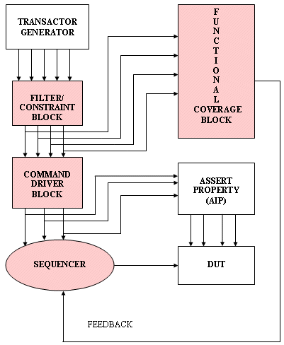
As we already had the Verilog testbench in place for our Directed Test cases, we implement the “constraint driven coverage based randomization†in System Verilog by reusing the Verilog based Transactor Tasks (Bus Functional Models) and utilizing System Verilog constructs as discussed below.

Figure-3: Enahnced and modified Verification environment
The above Figure-3 shows the layers added in the existing verification environment to implement the Constraint Random Verification environment.
The flow for preparing the test plan remains the same as before for the directed testing except that, now the focus is on implementing the random transactions and data streams which are valid for the DUT. The commands are random to the extent that they cover the corner case scenarios that can not be thought of during the directed verification. Cross-coverage of these transaction types is then performed, in order to ensure that all the combinations for op-codes and error conditions are exercised.
5.0 Building Blocks
5.1 Transaction based Stream (Packet) Generator
The Transactor generates high-level transactions like read/write with certain burst/size on some PORT. The term transactor is used to identify components of the verification environment that interface between two levels of abstractions for any transaction.

Figure-4: Code Snippet for the Packet Generator
5.2 Filter/ Constraint Block
Purely random test generations are not very useful because of the following two reasons-
1. Generated scenarios may violate the assumptions, under which the design was constructed.
2. Many of the scenarios may not be interesting, thus wasting valuable simulation time, hence -Random stimulus with the constraints.
 Figure-5: Random v/s Directed Approach
Hence the random generators should be constrained to generate the required stimulus sequences. Constraining the generators may involve defining sequences of data, but it also may involve coordinating multiple independent data streams onto a single physical channel/port or parallel channels/ports, each stream itself being made up of data sequence patterns.
The ability to constrain the generated data to create detailed stimulus scenarios tends to require more complex randomization process. It becomes more efficient to take few complex stimulus sequences as directed stimulus, and leave the bulk of the data generation to a simple randomization process.
This Filter/Constraint block generates the valid AHB transactions and allowed instructions for the platform. Below is the snippet of the code implementation of the constraint block.

Figure-6: Code Snippet for the Constraint Block
5.3 Command Driver Block
This block generates transactions, either individually or in streams. Individual meaning unit AHB packet and stream meaning multiple AHB packets for different transactor interfaces. Note that each of these commands may be derived several times or in several flavors till the Functional Coverage reaches 100.

Figure-7: Code Snippet for the Command Driver Block
The Command (Cn) is a combination of 1 or more number of unit AHB packets (Pn). Each packet (Pn) is targeted for different transactor interface.

Figure 8: Command Flow
5.4 Sequencer
Sequencer throws the command or a set of commands, to the DUT, depending on the weight or the probability of the scenario (command) at that point of time. Feedback of the Functional Coverage is used to determine the probability of the nth scenario and thus the output of the sequencer.

Figure-9: Code Snippet for the Sequencer Block
The below diagram shows, how a Sequencer generates the command considering its current weight which is initialized to ‘0’ at the beginning.

Where—
- F.C.nth -Functional Coverage of the nth behavior (set).
- Weight- Probability of selecting nth behavior (set).
- Scenario- Set of valid random instructions (BFM)
- Sequencer- Engine that triggers behaviors (set) based on its current weight.
Figure-10: Sequencer Methodology Overview
5.5 Functional Coverage Block.
To ensure that we hit every possible cross-coverage point it is required that we achieve a high functional coverage of the DUT. Also, any areas that were initially missed during random testing are easily highlighted by the functional coverage results.

Figure-11: Time v/s Functionality Tested
The functional verification requirements are translated into a functional coverage model to automatically track the progress of the verification project. A functional coverage model is implemented using a combination of covergroup. The choice depends on the nature of the available data sampling interface and the complexity of the coverage points.
Functional coverage is the primary director of the Verification strategy. It determines how well the test bench is fulfilling your verification objectives and measures the thoroughness of the verification process. A functional coverage model is composed of several functional coverage groups. The bulk of the functional coverage model for a particular design under verification will be implemented as a functional aspect of the verification environment.
The output of the Functional Coverage block is given as a feedback to the Sequencer which in turn decides the selection of the nth scenario.
The following points are kept in consideration for developing the coverage groups:-
- Coverage groups for the stimulus generated by the Generator.
- Coverage groups for the stimulus driven onto DUT.
- Coverage groups for the response received from the DUT.

Figure-12: Code Snippet for a Covergroup
5.6 Response and Protocol Checker (Assert Properties)
Assertions constantly check the DUT for correctness. These look at external and internal signals. The testbench uses the results of these assertions to see if the DUT has responded correctly.
In directed tests, the response can be hardcoded in parallel with the stimulus. Thus, it can be implemented in a more distributed fashion, in the same program that implements the stimulus. However, it is better to treat the response checking as an independent function.
By separating the checking from the stimulus, all symptoms of failures can be verified at all the times.
6.0 Conclusion
Keeping in view of the limited human resource and the stringent project deadlines, developing a object oriented verification environment in SystemVerilog over the existing Verilog environment felt advisable. Inclusion of the Constraint Random Verification significantly reduces the effort and time required to verify the complex behaviors.
The experience using SystemVerilog so far has provided us with an environment that is:
- Maintainable – The Common look and feel between related class types make it easy for team members to float from one functional area to another. The code is very modular with well defined ways to communicate between transactors.
- Controllable –The modular approach allow us to be more precise in determining expected values, thus minimizing false fails.
- Reusable – Core-level checkers, classes, tasks can be reused for system-level verification. In addition, the SystemVerilog skills developed on this project can be used in any future verification project that uses a high level verification language (HVL).
- The documentation and examples with VCS installation for getting started with SVTB, were very easy to comprehend.
7.0 Recommendations
Adopted methodology provided a robust verification architecture that produces more modular code with a higher degree of reusability. Code produced for one portion of the project can be used in other environments.
8.0 References
- http://www.inno-logic.com/education-systemverilog-methodology.htm
- http://verificationguild.com/modules.php
- ARM Synopsys Verification Methodology Manual (VMM) for SystemVerilog.
- http://www.eda.org/sv
- http://www.eda.org/sv-ieee1800/
