Gilles Depeyrot, Frédéric Poullet, Benoît Dumas
DOLPHIN Integration
ABSTRACT
The Verilog-AMS hardware description language [1] includes extensions dedicated to compact modeling, but does not define a reserved subset for compact modeling. This lack of specification combined with some SPICE related specificities are both responsible for the speed and memory consumption differences measured between simulations of Verilog-A compact models in Verilog-A simulators and SPICE simulators. That is the reason why, after presenting these differences, this paper [2] presents recommendations for developers of Verilog-A compact models who want to optimize their models for SPICE-like simulators and to facilitate the integration of said models into different simulators.
1. INTRODUCTION
Circuit design, in any semiconductor manufacturing process, is based on an accurate description of the electrical behavior of devices - transistors, diodes, resistors - in so-called "Spice models", also known as Compact Models. These models are used by analog circuit simulators, such as SPICE, to predict the electrical behavior of the circuit. Accuracy and performance of these models determines, to a large extent, the validity of simulations results with respect to measurements on silicon.
As semiconductor manufacturing processes move to smaller geometries, new physical effects impact the electrical behavior of devices. These effects must be modeled and require that additional equations be integrated into the compact models, which must then become available in analog simulators.
Usually, such modifications in compact models must be performed directly in the simulator source code (generally based on the C programming language) by each EDA vendor or through a proprietary application programming interface (API) of the simulator by the model developers. This cumbersome process is a barrier to the adoption of new compact models as it is both time consuming and very inefficient. Indeed, coding the model behavior into a low level language like C, or worse FORTRAN, implies calculating and coding the partial derivatives of currents and charges. And these derivatives are difficult to validate.
As a result, the majority of hand-coded compact models take months to develop and contain derivation errors which impact the accuracy of the simulation (mainly in small signal and in noise) and drastically impact the simulation time. Another drawback is that this approach is absolutely not portable; the code developed for one simulator cannot be used in another simulator without extensive customizations.
Over the last few years, the Verilog-AMS hardware description language [1], and specifically its analog-only subset, called Verilog-A, has been adopted by leading compact model developers, following the strategy judiciously promoted both by the GSA Modeling Working Group (MOS-AK and GSA Modeling) workgroup [3] and the Compact Model Council [4]. At the same time, the Verilog-A language was supported by most analog circuit simulators on the market. Despite Verilog-A language enhancements to provide better support for compact modeling [5], a performance gap exists between “direct†Verilog-A simulations and their SPICE simulations counterparts using models converted from Verilog-A to C by the means of a compact model compiler such as ADMS-XML [6][7][8].
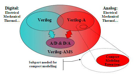
Figure 1: Verilog-A subset needed for compact modeling
The main explanation for this performance gap is that, as shown by figure 1, compact models only need a subset of Verilog-A; subset on which additional optimizations can and must be applied. This paper is specifically intended for compact model developers who describe their models in Verilog-A, and want to optimize their models for SPICE like simulators. Section 2 reports the results of the comparison between Verilog-A compact models running in
Verilog-A simulators and the same Verilog-A compact models running in SPICE simulators after conversion of the Verilog-A models into SPICE models. Section 2 also gives some hypotheses to explain the observed differences, while section 3 gives recommendations for writing efficient compact models for SPICE simulators with the three following main goals:
- Facilitate an efficient conversion for integration into different SPICE simulators.
- Reduce the memory footprint.
- Reduce the simulation time.
2. TEST RESULTS
Verilog-A has the potential to change the paradigm for compact model integration into SPICE like simulators [9]. In spite of performance improvements over the last years, Verilog-A simulators still remain far away from SPICE simulators in terms of memory consumption as well as in terms of simulation speed.
2.1 Test Bench description
The goal of the testbench is to test the model implementation, not the simulator engine solver. It must test the impact of the model implementation on the memory consumption and on the speed of transient simulation. For that, we force the number of iterations to be around 2550±5, we force the integration method to be trapezoidal, and we use the same tolerance (when possible). Thus, the solver has a constant impact on transient simulation speed.
The testbench is composed of an inverter chain: each inverter is loaded with the next inverter and a capacitor (always simulated in SPICE). We use three configurations to test the impact of circuit size on memory consumption and speed: 200 inverters, 2,000 inverters and 20,000 inverters.
We use only two models with default values for the parameters, one for the NMOS and another for the PMOS. The number of models is therefore far less than the number of MOS instances, just like in a typical SPICE simulation.
This testbench was applied on two SPICE/Verilog-A simulators, SMASH 5.15 our mixed simulator and Simulator B, one of our well known competitors.
This testbench was applied using the PSP model and the EKV3 model.
This testbench was run under the same OS (Windows XP 32bits) and on the same PC.
To compute the ratio between Verilog-A simulations and SPICE simulations, we take the best performances of each simulator to be less sensitive to their respective implementation.
We also ran this testbench on three successive releases of SMASH and Simulator B and have observed important variations in the Verilog-A performance results. Generally the performances progress but we also noted regressions. These evolutions prove that the EDA vendors are working hard on the integration of Verilog-A. Thus, the order of magnitude of the ratio between Verilog-A and SPICE is more important than exact values as this ratio is likely to change from one EDA tool release to the next one.
2.2 Memory consumption results
Table 1 shows the testbench results in terms of memory consumption. It must be noted that the EKV3 model is not yet available as a SPICE model in Simulator B.
Table 1: Memory consumption results
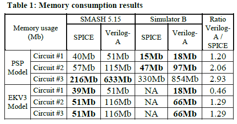
As SMASH runs with a graphic user interface, it consumes around 34Mb before loading the benchmark. Therefore, if we take this into account, the ratio increases and becomes (2.8; 3.5; 3.3) for the PSP model and (3.4; 3.9; 4.0) for the EKV3 model.
After analysis, SPICE consumes less memory for three main raisons:
a) As shown in figure 2, when converted into SPICE, the Verilog-A module is split into three structures: the instance (instantiated for each instance); the instance size (instantiated only once for all instances with the same size), and the model (instantiated only once for all instances that use the same model)
b) The variables of the module are not allocated in memory (heap), but are allocated as local variables in the stack when the instance is evaluated. Theoretically, this optimization is possible in Verilog-A, except for output variables which can be probed with system function $simprobe, as well as for variables which are used before they are assigned (hidden states).
c) Internal “extra†nodes are instantiated in Verilog-A and not in SPICE. This is the case for the PSP model which has two “extra†internal nodes dedicated to simulation of noise.
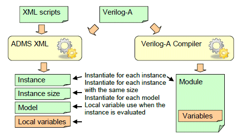
Figure 2: Memory decomposition in SPICE versus Verilog-A
The model/instance differentiation constitutes the main part of the memory differences. The study of the memory consumption of the SPICE models is given in table 2. The instance part consumes around 40 % of the memory. When the number of instances is far greater than the number of models, this memory consumption decomposition can explain a ratio up to 2.5 between Verilog-A and SPICE.
Table 2: Memory decomposition of the SPICE models

2.3 CPU time results
Tables 3 to 5 show the testbench results in terms of CPU time for the loading, the operating-point and the transient analysis. Again the ratio is very favorable to the SPICE simulations even for small simulations.
Table 3: CPU loading time results
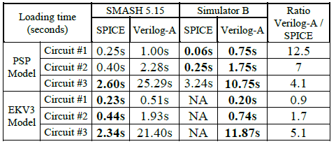
The load measurement was done on the second load, thus the compilation time of the Verilog-A model is not included in these measures. As the model is initialized only once in SPICE, the model/instance differentiation can explain a ratio up to 2 between Verilog-A and SPICE.
Table 4: CPU operating point time results
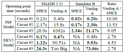
The execution speed differences during operating-point analysis are mainly due to:
- Derivation/integration which requires one additional node. Even if the derivation is zero during operating-point, the additional node increases the matrix size and slows down the resolution.
- At each iteration of the operating-point analysis, the Verilog-A simulator executes the code corresponding to the model/instance initialization or temperature adaptation, while the SPICE simulator does not.
- Collapsible nodes that are used for instance to collapse nodes when access resistances are not created.
Table 5: CPU transient time results
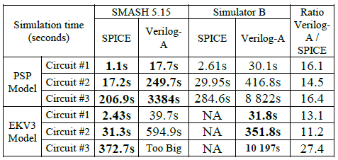
The execution speed differences during transient analysis are mainly due to:
- Derivation/integration which requires one additional node. The frequent case in compact models is the case of charge derivatives which can be optimized without adding an extra node.
- Bypass/linearization, where, in SPICE for small variations, the compact model is replaced by a linear model which is far faster.
- At each iteration of the transient analysis, the Verilog-A simulator executes the code corresponding to the model/instance initialization or temperature adaptation, while the SPICE simulator does not.
- Hidden states for variables that depend on the previous point and output variables. At each iteration of the transient analysis, the Verilog-A simulator initializes the variables with the previous value, while the SPICE simulator does not.
- Collapsible nodes that are used for instance to collapse nodes when access resistances are not created.
The speed impacts of the Verilog-A/SPICE implementation differences above are summarized in table 4. The differences marked in bold have an impact that increases with the size of the circuit.
Table 6: Speed impact of the Verilog-A/SPICE implementation differences

3. RECOMMENDATIONS
3.1 Subset of Verilog-A
The Verilog-AMS hardware description language [1] is a general-purpose behavioral language for analog and mixed-signal systems available for both electrical and non-electrical systems description. As such, it includes a number of features that are not suited for compact modeling. Moreover, contrarily to the Verilog standard, where the IEEE has defined syntax and semantic rules for both simulation and synthesis (IEEE1364-2001[9] and IEEE 1364.1-2002[11]), the Verilog-AMS hardware description language does not define a subset reserved for compact modeling.
Furthermore, the subpart of Verilog-AMS usable for compact modeling is reduced if we add constraints related to its integration into different electrical simulators. Here after this subpart we recommend:
- Language: limit to the use of Verilog-A; digital Verilog-HDL is not relevant here.
- Data types: limit to the use of integer and real data types.
- Use only scalar, do not use vectors or arrays.
- Contribution statements: limit to the use of current (flow) versus voltages (potential).
- Port branches: do not access currents through module ports.
- Analog operators: limit to the use of ddt, ddx and idt, limit the order to one. Do not combine these operators between themselves.
- Do not use analysis functions.
- Do not use AC stimulus.
- Do not use “impure†system tasks and functions except for debugging purposes or to report an error or a warning. When possible we recommend restricting the usage to the following system tasks and functions: mathematic system functions, simulation control system tasks, $temperature, $vt, hierarchical parameter system functions, and explicit binding detection system functions.
- Do not use analog event control statements.
- The compact model is not hierarchical; do not use module instantiation or any hierarchical structures.
3.2 Spice specificities
The previous recommendations are quite generic concerning compact modeling, and weakly related to the SPICE simulators themselves. We don’t intend to normalize the writing of compact models, but to facilitate their integration into different SPICE simulators. We recall that the objectives are threefold:
- To reduce human interventions and the associated risks of having different behaviors in different simulators and facilitate an efficient conversion for integration into different SPICE simulators.
- To reduce the memory footprint to be able to load several tens of thousands of transistors in a conventional SPICE simulator.
- To reduce the simulation time, as it is of critical importance for the analog designer that the compact models run as quickly as possible in the SPICE simulator.
- Completeness: The model should be complete which means that it should contain everything needed by the final user for analog design. For instance, it should include equations for NPN and PNP for a bipolar, or NMOS and PMOS for a MOS.
- Port order: SPICE primitives use ordered port connections; keep this order in the model, and use common port names (i.e. drain, gate, source, bulk for MOS primitives for instance).
- Disciplines and natures: limit to the use of electrical discipline with voltage and current natures.
System tasks and functions: limit to the use of explicit binding detection system functions, $vt, $temperature, and $mfactor.
- Common instance parameters: SPICE primitives have predefined or common parameters; for instance W, L, AD, AS, PD, PS and NF for MOS or AREA for bipolar. Use the common parameter names and tag these parameters with a dedicated property, for example (* spice="area" *) for the parameter AREA of a bipolar. Do not change the definition of such parameters so that the same netlist can be used with different models. Special care should be taken with the multiplicity factor: as Verilog-A already normalizes this parameter with the hierarchical system parameter $mfactor, we recommend to use it and not to add an extra parameter.
- Instance/Model parameters: contrarily to Verilog-AMS, SPICE makes a clear distinction between instance and model parameters. This distinction is needed to be able to define the characterization strategy, and to develop the tools used to characterize the semiconductor manufacturing processes and extract the model parameter sets. This distinction can be specified with a parameter attribute, for instance: (* type="instance" *). Note that it is not necessary to mark both, instance and model, since if a parameter is not an instance parameter it is necessarily a model parameter. Furthermore, instance size related parameters can be automatically extracted.
- Parameter description: for each instance and model parameter, give a short description using the info attribute, and specify its unit if any using the attribute unit. Example: (* desc="C-S punch-through voltage", unit="V" *) parameter real vpts = 100 from (0:100];
- Output variables: they can be printed or plotted by SPICE simulators. We recommend to define common variables used by analog designers such as gm, gmds, gds or transistor state for MOS transistors, or gm, gpi, gmu, go, beta and ft for bipolar transistors. At the difference of other variables, allocated as local variables in the stack, output variables should be available between two Newton-Raphson iterations and will be allocated in the heap. As defined by the Verilog-AMS LRM, an output variable is a module scope variable with a description or units attribute, or both. For example: (* desc="transconductance" unit="A/V" *) real gm;
- Functional sections: compact models have a large number of equations, which are not all needed at every phase of every type of analysis. Theoretically, starting from the dependency tree and the distinction between model and instance parameters, model builders should be able to determine which equations are needed for each phase of each analysis. In practice, model builders are far from this objective. So, to help model builders generate more efficient SPICE simulator code, we recommend splitting the code at least into the following four sections using named blocks. As theses sections generally correspond to different phases of the compact modeling development, the split is not too restrictive:
- Model initialization: This section contains initialization of the model; this means initialization of every variable needed for the simulation but constant during the simulation and exclusively function of the model parameters and simulator parameters such as temperature.
- Instance initialization: This section contains initialization of the instance; this means initialization of every variable needed for the simulation but constant during the simulation and exclusively function of the model or instance parameters and simulator parameters such as temperature.
- Instance evaluation: This section contains the kernel of the model, it outputs current on ports in function of voltages applied on ports.
- Noise: This section contains the noise contribution.
- Noise types: in SPICE, noise is generally divided into three categories: thermal, flicker, shot noise. When possible, we recommend to use one of these categories for specifying the noise source label in Verilog-A.
- Port current probe: avoid use of I(<port_name>) probes to define a current contribution. In some implementations, it will add an extra node which penalizes simulation speed.
- ddt of ddt: avoid use of derivative or integral of order greater than one. They are generally implemented by adding extra nodes.
- Pure and impure: for allowing SPICE optimizations such as bypass or linearization, the instance evaluation section should be pure. This means that when called with the same port voltages and charges, the evaluation should always return the same port currents, whatever the simulation time. In computer language, a pure function is a function with "no side effects". To that end, impure functions, such as random, should not be used in the evaluation section and variables should be initialized before they are used in an expression.
- Collapsible nodes: collapsible nodes have the benefit that they reduce the size of the system matrix. This is particularly valuable in simulations where there are numerous instances of a device, because reducing the system size increases the simulation speed. They should be defined during the instantiation phases, so they should be function of model or instance parameters only. Avoid collapsing two ports, or one port and the ground, as in general, it will be implemented as an extra node. Contrarily to other modeling languages, such as MAST [12], the Verilog-AMS 2.3.1 LRM does not yet specify the syntax and conditions for collapsing nodes. A common “idiom†for that [13] is:
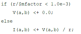
This “idiom†has several drawbacks, one of the main ones being that the “if†statement can be repeated many times in the model which is a potential cause of error. That is why we propose another syntax which is based on the usage of attributes:

Such an attribute can be automatically handled during conversion of Verilog-A models into SPICE models, for instance when using the ADMS-XML compact model compiler.
4. CONCLUSION AND PERSPECTIVES
With the SPICE compatibility extensions of the Verilog-AMS Language Reference Manual (LRM) version 2.3.1 [1], Verilog-A has the potential to revolutionize the paradigm of analog design of integrated circuits and totally replace SPICE.
The achievement of this goal depends on the adoption of Verilog-A by all the actors concerned: final users, semiconductor foundries, compact model developers as well as EDA vendors. But both final users and semiconductor foundries cannot accept degradation in simulation speed or loss of functionality. This paper introduces the sub-set of Verilog-A needed to write efficient compact models for different Verilog-A simulators. And, as SPICE simulators remain faster than most Verilog-A simulators, this paper presents some guidelines to help compact model developers improve the integration of their Verilog-A models into SPICE simulators while reaching the speed and the functionality of C based compact models.
A recent study [14] shows that under some conditions, some Verilog-A simulators can be as efficient as SPICE simulators. The ball is now in the camp of the standard groups and EDA vendors to make Verilog-A simulators as fast as their SPICE counterparts, as well as to allow Verilog-A to address the challenges of deep submicron processes such as process dispersion, dynamic degradation, power consumption, system-level complexity…
REFERENCES
[1] Accellera Verilog Analog Mixed-Signal Group: http://www.accellera.org/activities/verilog-ams
[2] This work is supported by the European Commission FP7 under contract number 218255 (COMON)
[3] GSA Modeling Working Group: http://www.mos-ak.org/
[4] CMC - Compact Model Council: http://www.geia.org/index.asp?bid=597
[5] L. Lemaitre, G. Coram, C. McAndrew, K. Kundert, “Extensions to Verilog-A to support compact device modelingâ€, Proc. 2003 IEEE International Workshop on Behavioral Modeling and Simulation (BMAS 2003).
[6] L. Lemaitre, C. McAndrew, S. Hamm, “ADMS - Automatic Device Model Synthesizer,†CICC 2002.
[7] L. Lemaitre, C. McAndrew and W. Grabinski, “Standardization of Compact Device moding in High Level Description Languageâ€, Nanotech 2003, Vol. 2
[8] ADMS-XML - Automatic Device Model Synthesizer: http://mot-adms.sourceforge.net/
[9] M. Mierzwinsk, P.O. Halloran, B. Troyanovsky and R. Dutton, “Changing the Paradigm for Compact Model Integration in Circuit Simulators Using Verilog-Aâ€, Nanotech 2003, Vol. 2
[10] “1364-2001 IEEE Standard Verilog Hardware Description Languageâ€, IEEE, Pascataway, New Jersey. Copyright 2005.ISBN:0-7381-2827-9.
[11] “1364.1-2002 IEEE Standard for Verilog Register Transfer Level Synthesisâ€, IEEE, Pascataway, New Jersey. Copyright 2002. ISBN:0-7381-3502-X.
[12] OpenMASTâ„¢ is the open source of the MAST language: http://www.openmast.org/
[13] M. Mierzwinski, P. O'Halloran, and B. Troyanovsky, “Developing and releasing compact models using Verilog-Aâ€, MOS-AK San Fran 2008
[14] G. Coram and M. Ding, “Recent Achievements in Verilog-A Compact Modelingâ€, MOS-AK/GSA Baltimore 2009
