G. Karmakar, Ashutosh Kabra, R. K. Patil
Bhabha Atomic Research Centre
Mumbai, India
Abstract:
This paper attempts a journey right from configuring a PLC, writing application program to code generation along with run-time configurations and RTOS abstraction for embedding it into PLC hardware using a typical control Logic application. The IEC 61131-3 languages Function Block Diagram (FBD) and the corresponding ST (Structure Text) has been used as vehicles for this tour.
INTRODUCTION
Programmable Controllers (PLC) are the backbone of most automation projects. PLCs are used for controlling purposes in various industries like power generation, steel production, chemical, petrochemical, Nuclear Power plants etc. A Programmable Controller (PLC) is an industrial computer control system that continuously monitors the state of input devices and makes decisions based upon a program to control the state of output devices. PLC is an example of a real time system since output results must be produced in response to input conditions within a bounded time. In the past many vendors for PLC systems used their own programming languages which were incompatible with others. To enhance reusing of components, compatibility and interoperability among different product, the IEC 61131 standard was introduced to unify the main different approaches. Third part of IEC 61131 standard specifies the syntax and semantics of a unified suite of programming languages for programmable controllers (PCs), of which most widely used are Function Block Diagram (FBD) and Structured Text (ST). In this paper, we describe a typical control Logic application for demonstration of configuring a PLC, writing application program and code generation along with run-time configurations and RTOS abstraction for embedding it into PLC hardware. The programming language ST (Structured Text) and the corresponding FBD have been used throughout the paper.
THE STUDY EXAMPLE
A. Problem Definition
A simple example of controlling a pump P1 and its discharge valve V1 and sending information to any device (say a SCADA station) on demand has been taken as the study example.
The following Use Cases specifies the requirement:
Use Case1: Read Inputs
Read the following field Inputs
- P1 START Push Button (PB) status
- P1 STOP Push Button (PB) status
- V1 OPEN Push Button (PB) status
- V1 CLOSE Push Button (PB) status
- P1 ON/OFF status
- Read P1 discharge pressure
It is a time driven task: Read every 10 ms Use Case2: Control Interlocks
- The pump P1
- Will start if START PB is actuated and will be latched.
- Will stop either if the STOP PB is actuated or if the P1 discharge pressure is high. Obviously, any of these conditions will de-latch the START PB actuation event.
- The Valve V1
- Will open either if the V1 OPEN is actuated OR (if the Pump is started AND 3 second has been elapsed).
- Will close if the V1 CLOSE is actuated provided the pump P1 is not running.
Use Case3: Communication Slave/Server
On Query from any external device it will send Response data. The protocol details are not part of this high level programming.
THE DOMAIN MODEL OF PLC
The domain model of a PLC in figure 1 below depicts the various software modules that make a PLC.
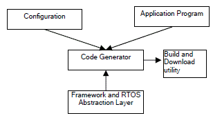
Figure 1: PLC domain model
SOFTWARE MODEL AND BUILDING BLOCKS OF IEC 61131-3
IEC 61131-3 software model consist of elements which are programmed using the languages defined in this standard and configuration elements, namely configurations, resources, tasks, global variables and instance-specific initializations, which support the installation of programmable controller programs into programmable controller systems. Software Architecture of IEC 61131-3 PLC is shown in fig. 2.
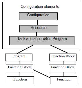
Figure 2: Software Architecture of IEC 61131-3 PLC
A. Configuration, Resource and Task
At the highest level, the software for a particular control application is contained in a configuration. Configuration is used to group all resources of the PLC system together. It also provides means for data exchange between them.
A resource is the processing facility, able to execute IEC programs. It is defined in order to assign task to the physical resources of a PLC system. One or more resources can be defined within a configuration. Configuration and resources do not contain instructions like POUs, but solely define the relations between their elements.
Configurations and resources can be started and stopped via the “operator interfaceâ€, “programming, testing, and monitoringâ€, or “operating system†functions defined in IEC 61131- 1. The starting of a configuration shall cause the initialization of its global variables, followed by the starting of all the resources in the configuration. The starting of a resource shall cause the initialization of all the variables in the resource, followed by the enabling of all the tasks in the resource. The stopping of a resource shall cause the disabling of all its tasks, while the stopping of a configuration shall cause the stopping of all its resources.
Task is defined as an execution control element which is capable of invoking, either on a periodic basis or upon the occurrence of the rising edge of a specified Boolean variable, the execution of a set of program organization units, which can include programs and function blocks whose instances are specified in the declaration of programs. Like any PLC application, other than assigning Programs and/or functions to tasks, we also need to configure the requirement of I/O hardware and its type. For our study example, one Digital Input Card, One Digital Output Card and one Analog Input Card are required.
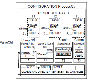
Figure 3a depicts the PLC configuration for our study example in FBD.
Figure 3a: Configuration ProcessCtrl in FBD The configuration written in ST is shown in figure 3b.
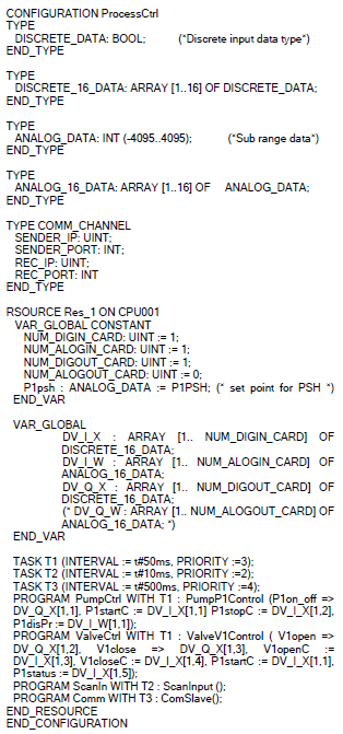
Figure 3b: Configuration ProcessCtrl in ST
B. Structure of the building blocks: The Program Organisation Units (POUs)
Function, Function Block and Program are the three Program Organization Units (POUs) defined by the IEC 61131-3. A POU contains a declaration part and body.
1) Declaration of variables: IEC 61131-3 standard uses variables to store and process information. Variables can be assigned to a certain I/O address (using the keyword AT) and can be battery backed against power failure (using the keyword RETAIN).
Each declaration of a program organization unit contain at its beginning at least one declaration part which specifies the types and the physical or logical location (if needed) of the variables used in the organization unit.
2) Body of POU: The algorithmic behaviour of POU is defined in one of the five languages defined by the standard: FBD (Function Block Diagram), LD (Ladder Diagram), ST (Structured Text), IL (Instruction List) and SFC (Sequential Function Chart). FBD is the popular application domain language. The ST language has a comprehensive range of constructs for assigning values to variables, calling functions and function blocks, creating expressions, for conditional evaluation of selected statements and for iteration.
C. Programs
A program is defined in IEC 61131-1 as a “logical assembly of all the programming language elements and constructs necessary for the intended signal processing required for the control of a machine or process by a programmable controller system.†Functions and Function Blocks within a program are able to exchange data through software connections. A program can be written in any of the defined programming languages. A program can also read and write to input/output variables and communicate with other programs. The execution of different parts of a program, for example selected function blocks, may be controlled using tasks. For our study example, we have following programs
1) PumpP1Control
The PumpP1Control program in FBD is shown in figure 4.
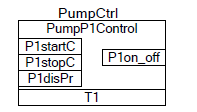
Figure 4: FBD for program PumpP1Control
2) ValveV1Control: Both the FBD and the
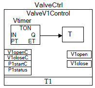
Figure 5a: program ValveV1Control in FBD
corresponding ST program of valve control are shown in figure 5a and 5b respectively. ValveV1Control uses on delay timer TON in addition to other ST programming features.
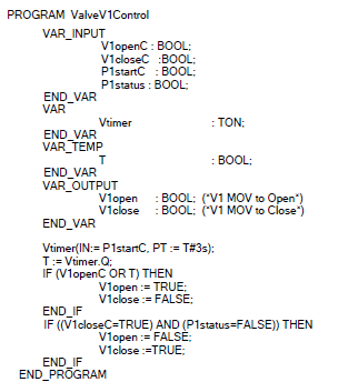
Figure 5b: program ValveV1Control in ST
3) ScanInput
The ScanInput program in FBD is shown in figure 6.
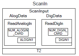
Figure 6: FBD for program ScanInput
D. Function and Function blocks
These are the basic building blocks, containing a data-structure and an algorithm. For our study example,
1) The required function blocks are
• ReadAnalogIn
In any PLC, reading inputs from physical I/O cards is unavoidable. The ReadAnalogIn function block in FBD is shown in figure 7.
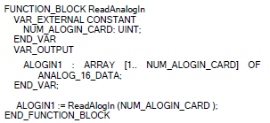
Figure 7: function block ReadAnalogIn in ST
• ReadDigitalIn
• TON
2) The required functions are
• ReadAlog : ST code of this function is shown in figure 8.

Figure 8: function ReadAlog in ST
• ReadDig
E. Global and direct variables
A global variable can be declared at program level, resource level or configuration level. Global variables provide a means for transferring data and information between programs or between function blocks residing within different programs. Directly represented variables (e.g. %IX1.1, %IW1.1, %QX1.1) are used to address the memory locations within a PLC directly.
Global variables in our study example program are as shown in the code for Configuration
F. Communication Model
There are several ways through which values of variables can be communicated among software elements.
1) Variable values within a program can be communicated directly by connection of the output of one program element to the input of another as shown in figure 9.

Figure 9: Dataflow connection within a program
2) Variable values can be communicated between programs in the same configuration via global variables as shown in figure 10. These variables are declared as GLOBAL in the configuration, and as EXTERNAL in the programs.
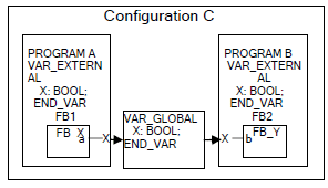
Figure 10: Communication via GLOBAL variables
3) Variable value can be communicated between different parts of a program, between programs in the same or different configurations, or between a programmable controller program and a nonprogrammable controller system, using the standard communication function blocks as shown in figure 11.
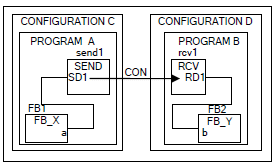
Figure 11: Communication function blocks
For our study example, Communication function blocks model will be used for communication with outer world. For this purpose, the required Program and FBs are shown in figure 12a (FBD) & figure 12b (ST).
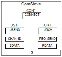
Figure 12a: Program ComSlave in FBD
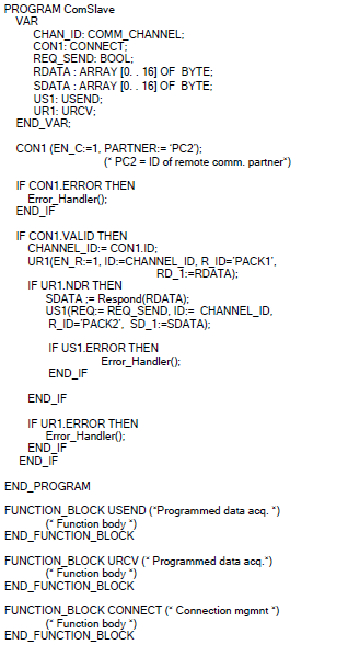
Figure 12b: Program ComSlave in ST
MAIN ADVANTAGES OF IEC 61131-3
A. Convenience and security with variables and data types
- Local and global variables are used instead of hardware addresses. The programming system automatically distinguishes between global variables and variables local to a POU.
- Variables can be declared retentive (RETAIN qualifier) to retain the previous value on warm start.
- Limits of array indices and ranges of variables values are checked by the programming system as well as by the PLC system at run time.
B. Blocks with extended capabilities
- Blocks (POUs) designed to be independent of the target system. These makes it possible to have reusable (libraries) blocks for multiple platforms.
- Efficient assignment of block parameters by means of variety of mechanism for passing data to and from blocks.
- VAR_INPUT : Value of a variable
- VAR_IN_OUT : Pointer to a variable
- VAR_OUTPUT : Return value
- VAR_EXTERNAL: Global variable of another POU
C. PLC configuration with run time behaviour
Tasks and programs are assigned to the controller hardware at the highest level of a PLC project (the configuration). This is where the run time properties (periodicity/triggered, priority) and interfaces to the outside and I/Os are defined for the various program parts.
RTOS ABSTRACTION LAYER
IEC 61131-1 states that the operating system function of Programmable Controller is responsible for the management of internal PLC-system interdependent functions (configuration control, diagnostics, memory management, application programme execution management, communication with peripherals, etc.).
We are discussing Programmable Controller as Real-time systems and hence it is important to discuss the Real-Time Operating System (RTOS) and its interface to the PLC application software.
The runtime programs are associated to tasks, which run under a RTOS. To make the translated implementation source code RTOS-independent, a framework is developed, which provides an RTOS Abstraction Layer (ROSAL). This ROSAL will serve as the only interface to the RTOS and will be the only OS-dependent package within the framework. A layered approach is shown in figure 13.
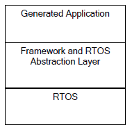
Figure 13: The Layered approach
The RTOSAL consists of a set of interfaces that provides all the required RTOS services for the application
- Tasking services
- Synchronization
- Message queues
- Communication port
- Timer service
The RTOSAL supports each of these services by implementing thin wrappers around real time operating system entities, adding minimal overhead.
CONCLUSION
We are all aware that understanding a standard and making a product based on it is best done by a guided tour of it using a single study example from the beginning to the end. It is our hope that this study will be helpful in IEC-61131-3 based software development projects.
ACKNOWLEDGEMENTS
The authors thankfully acknowledge Shri Jose Joseph, Head CSES, RCnD, Shri B.B.Biswas, and Head RCnD for giving us the opportunity to work on the PLC development. We also thank Shri G.P. Srivastava, Director E&I Group for his continued support to our work.
REFERENCES
[1]. IEC. Programmable Controllers - Part 3: Programming Languages, IEC 61131-3. Technical Report, International Electro technical Commission - Geneva, Second Edition, 2003.
[2]. IEC. Programmable Controllers - Part 5: Communications, IEC 61131-5. Technical Report, International Electro technical Commission - Geneva, 2000.
[3]. K.H. Jhon, M. Tiegelkamp. IEC 1131-3 Programming Industrial Automation Systems , Springer, 1995.
[4]. IEC. Programmable Controllers - Part 1: General Information, IEC 61131-1. Technical Report, International Electro technical Commission - Geneva, Second Edition, 2003.
[5]. G. Karmakar, A. Kabra, J. Joseph, B. B. Biswas, R. K. Patil. PLC Configuration and Programming experience using ST Language. DAE-BRNS Seminar on Applications of Compute rand Embedded Technology, VECC Kolkata, Oct.28-29, 2009.
