By Olivier Montfort, Dolphin Integration
Abstract.
The memory hierarchy (including caches and main memory) can consume as much as 50% of an embedded system power. This power is very application dependent, and tuning caches for a given application is a good way to reduce power consumption.
However application programs are complex and include many subroutines, each of them having their own optimal cache configuration. We developed a low power dynamically reconfigurable cache controller and its simulator called Cache Evaluation Software.
This simulator allows user to specify cache reconfigurations within the application program and evaluates time and power consumption for each configuration phase taking into account reconfiguration costs. It allows a fast assessment of optimal cache configuration for subroutines and demonstrates that power consumption of the memory system can be reduced by 83% thanks to this approach. We also used it to simulate our self–configurable cache and proved a power reduction of 70% for the memory system and thus avoiding the difficult task of choosing the configuration parameters of the cache.
1 Introduction
Because of the increasing complexity of systems-on-chip, energy consumption becomes a major concern in embedded systems. In microprocessors systems, the memory hierarchy can consume as much as 50% of the total energy [1] and a good design of the cache architecture can significantly reduce this energy. Many architectural techniques are available to reduce the power consumption of cache systems [2] [3] [4]. Furthermore the energy consumed by memory hierarchy is very dependent on the application. And tuning the cache capacity, the associativity and the cache line size for each given application is one effective method to greatly reduce energy. A fully configurable cache allows to select the lowest consuming cache configuration for each given application and a gain of 40% compared to a traditional four-way set associative cache have been demonstrated [5].
However, real application programs are made of several subroutines that have individually an optimal cache configuration. Tuning a cache is no more consisting in selecting the most appropriate configuration for one application but for every subroutine. This requires to be able to assess the power consumption of the memory subsystem (cache + main memory) while executing an application that reconfigures dynamically the cache architecture.
In our work, we developed a dynamically configurable Instruction cache controller model coupled with an Instruction Set Simulator that allows a fast assessment of the power consumption and of the execution time of the memory subsystem.
The cache controller includes some control registers that can be modified by the application program during execution to update cache configuration. The extra consumption due to reconfiguration or to cache flushes is also taken into account by the model. The whole simulation system allows to easily add reconfiguration directives inside application program and to find the optimal cache configuration for each subpart of the program.
Despite the help provided by the simulator, the task of tuning the cache can be time consuming and the developer needs to have a good knowledge of both application program and cache system. This is often not the case especially in complex SoCs where software developers are not fully aware of the hardware architecture.
To avoid this step of cache setting, we have developed a self-configurable cache whose performances can be easily evaluated using our Cache Evaluation Software. This cache is able to dynamically update its configuration (associativity and cache line size) to reach minimal power consumption.
The rest of this paper is organized as follows. In Section 2, we demonstrate the interest of configurable cache. In Section 3, we present the architecture of our Cache Evaluation Software. Our experiments results will be given in Section 4 and in Section 5 we conclude the paper.
2 A configurable cache for the power consumption issue
The power consumption of memory hierarchy is very dependant on cache configuration and application program.
The main configurable parameters of cache system are the capacity of the cache memory, the associativity and the cache line size. In our study we only focus on associativity and cache line because these parameters have a great impact on dynamic power consumption for configurable caches. The capacity of the cache memory has also an impact. Bigger capacities of cache memories are, bigger the power consumption is. However, the dynamic configuration of cache size consists in using several static RAMs that can be shut down separately depending on the selected cache size. This enables to reduce static power, but has no impact on dynamic power. In the process used for our study (0.18um) static power is negligible and configuring cache size makes no sense.
Therefore, in this study a cache configuration is given by the couple associativity and cache line size.
When increasing the cache associativity, the number of accesses to main memory will decrease because of increasing hit ratio, but in the same time, the number of accesses to internal cache memories (tag and data) will increase.
When increasing the cache line size, the number of accesses to main memory will increase but internal accesses will decrease. Finding the lowest consuming configuration for the cache will then consist in finding a trade-off between main memory energy consumption and the cache memories (tag and data) energy consumption. This trade-off will be different for each program. A program with high spatial locality would benefit from a high cache line size whilst a program with high temporal locality will have good results if the cache has a higher associativity. Generally, programs are made of many subroutines that are dedicated to a specific task. Each of these subroutines may not have the same optimal cache configuration. Using a runtime configurable cache controller allows specifying the optimal configuration for each part of the program and saving an important amount of energy.
3 A solution for an efficient evaluation: the Cache Evaluation Software
The Cache Evaluation Software is a simulation framework that enables to evaluate the performances of a MCU and its memory hierarchy.
It is made of a configurable cache controller model connected through an Application Programming Interface to the Instruction Set Simulator of a processor.
3.1 Low Power Configurable Cache Architecture
Our main objective was to design the lowest consuming instruction cache architecture, with configurable associativity and cache line size using standard commercial static RAM for data and tag memories. The choice of using standard static RAM allows an easy portability of the cache to every technological process where static RAM are available and thus without requiring extra design work. It also allows a fine optimization of the memory hierarchy performances by selecting the most appropriate static RAM. C. Zhang [5] proposes a configurable cache whose associativity can be configured as four, two or one way set associative and cache line size as 16, 32 or 64 bytes using the full capacity of the cache. C. Zhang implementation needs a modification of the decoding logic of tag and data memories and thus prohibits the use of standard static RAM. Instead of modifying internal decoders we decided using four static RAM for tag memory and a unique static RAM as data with external logic enabling to remap address depending on the chosen associativity.
For cache line size configuration, we used the same scheme as C. Zhang.
To further reduce the power consumption we have added a mechanism to avoid reading again tag memory when accessing consecutively to the same cache line.
We also added optional counters to count the number of CPU requests, tag memory accesses, data memory and background memory accesses and a signal to indicate an overflow of CPU requests counter. These counters are accessible through an optional monitoring interface that can be connected on CPU data bus, and the overflow signal can be connect to an interrupt input of the processor. In the case of self-configurable cache, we use the overflow interrupt signal to launch a cache configuration analysis and the value of these counters to determine the optimal cache configuration.
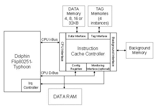
Figure 1. Simulated System: MCU + Cache + Memories
3.2 Simulator Architecture
The objective of the simulation is to evaluate the performances of an embedded CPU system including the CPU, an instruction cache controller and its associated memories (tag and data), and the background memory (Figure 1) thanks to an interface that allows the users to:
- Easily modify, compile and run its own application program (written in C or assembly)
- Assess the execution time of the application
- Assess the energy consumed during the execution
- Add directives directly within the code to reconfigure the cache controller and measure the effect on the performances.
We first developed a behavioural model of the system including the low power cache controller, the tag and data memories and the background program memory in C++. The model is “CPU request†accurate. For each CPU access (sending of an address to the model), the data read is evaluated and the number of read or write accesses on each cache memory interface (tag and data) are evaluated as well as the number of hits and misses.
Cache reconfiguration and cache flushes can also be programmed by setting the corresponding bits in control registers. The potential loss of data due to reconfiguration is modelled as well as the memory access needed for a cache flush.
This model enables also the setting of CPU and background interface bus width, the addressable space and the size of the cache before running a simulation.
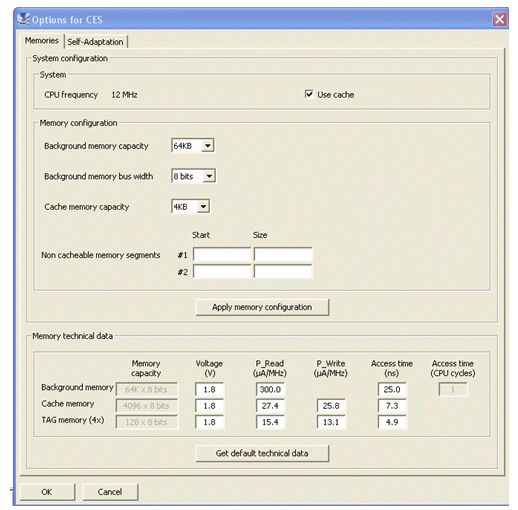
Figure 2. Cache Configuration Menu
This model is connected to a commercial Integrated Development Environment (IDE) through an application programming interface. The IDE already includes a friendly graphical user interface, all the tools for C and assembly compilation, and an instruction set simulator of our Flip80251-Typhoon CPU (Figure 3). We added dedicated cache tools: an extra menu to configure cache parameters and memory performances (Figure 2) as well as a window to display and analyse cache performances.
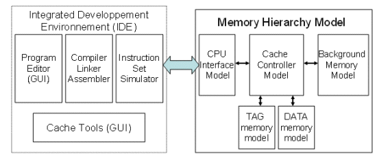
Figure 3. Cache Simulator Architecture
3.3 Execution Time and Power Estimation
The performances of the system are evaluated using both the calculation made by the C model and the ISS.
For the energy evaluation, only the accesses to data, tag and background memories are modeled because it is sufficient to compare the different cache architectures. However for a complete energy analysis of the system, the CPU, cache logic and data memory energy could be modeled. [8] [9]
The total energy is obtained by multiplying the energy per access by the number of accesses for each memory and each access type.
Thanks to the number of hits and misses, we are able to evaluate the time required by the cache to provide a data to the CPU. The impact of the pipeline is taken into account by using the duration of each instruction given by the ISS.
The model also uses the access time of data and tag memories to check if the specified frequency can be reached.
Thanks to the combination of ease-of-use IDE and an accurate cache model, users are able to easily tune cache systems for complex applications.
4. Application and Results
4.1 Benchmark Hidebench
Application programs for embedded systems have an increasing complexity and are made of many subprograms that can be very different. For example, actual mobile phones contain many different applications (phone, web access, decoding videos, GPS …). Simples benchmark as MPEG-4 or JPEG-2000 of Mediabench suite [6] are not representative of the variability of an application program, and thus do not enable to highlight the interest of a configurable cache.
For the need of the evaluation, we developed our own benchmark, “HideBenchâ€. This benchmark is made of subroutines that are called sequentially. Each subroutine is designed to favour a cache configuration. For example, in the Figure 4, the routine asm_func_1way_32bytes, is designed to be optimal with a direct-mapped cache with a cache line size of 32 bytes. The sequence of the subroutines call can be changed for exhaustive tests.
In this article, we only present the results for one given sequence of configuration (Figure 4).
All results are given for a simulation with Dolphin Flip80251-Typhoon CPU, using a 4 kBytes cache and a 64 kBytes Embedded Flash as Background Memory. The memory performances are given for a TSMC 0.18um process (Tag and data memories are Dolphin 0.18um Pluton SRAM).
In this system, the power consumption ratio between data cache memory and background memory is about 10. It’s an average ratio for system with embedded memory, but it allows a significant reduction of memory hierarchy energy compared to a system without cache (energy divided by 3 up to 7 depending on application). In systems with external background memories (DRAM, external Flash), the ratio can reach up to 50. In these cases using a cache allows a drastic energy reduction (divided by 15 up 30 depending on application).
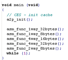
Figure 4. Hidebench subroutines sequence
4.2 Dynamic Tuning Results
Figure 6 and Figure 7 show respectively the energy consumed for Hidebench execution and the execution time depending on the configuration of the cache controller. The first columns shows the performances of the application with a given cache configuration that stay the same all along execution. The column “dynamic†corresponds to the performances when optimal configuration is selected for each subroutine (the column “self-adaptation†is described in 4.3). The cache evaluation software allows to evaluate energy consumed by each subroutine in all cache configurations (associativity and cache line size) and to determine the low consuming cache configuration. To simulate the effect of reconfiguration, we modify the application program to insert reconfiguration directives (Figure 5). These directives allow writing cache configuration registers to change cache configuration during program execution.
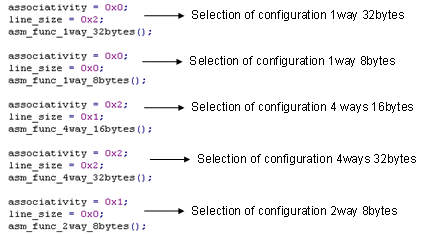
Figure 5. Hidebench code with reconfiguration directives
We notice that dynamic tuning enables an energy reduction from 7% up to 83% compared to a cache with a fixed configuration. Regarding the execution time, the configuration using dynamic tuning is as fast as the fastest fixed cache configuration (4-ways, 32 bytes) and 6% fastest as the slower fixed cache configuration (1-way, 8bytes).
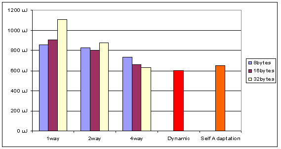
Figure 6. Hidebench Energy Consumption depending on cache configuration
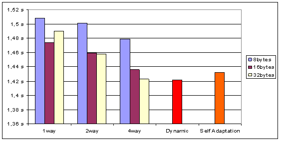
Figure 7. HideBench Execution Time depending on cache configuration
4.3 Self-Adaptive Cache
The tuning allows an important energy saving, but in the case of complete applications, this operation can become very long and complex, or even impossible if the software developer does not know the details of the hardware architecture, which is often the case. If we look again at the case of mobile phones, developers create applications compatible with many phones without any idea of hardware architectures.
In this way, we developed an algorithm that is able to determine the lowest consuming cache configuration all along application execution thanks to the value of the monitoring counter described in 3.1 and power consumption estimation of the memory connected to the cache.
The simulations results are in the columns “Self-Adaptation†of the Figure 6 and Figure 7. The power consumption and the execution time are very close to the value of the best cache configuration (2% more consuming and 1% slower) and, compared to the worst configuration we have a very good gain (70% less consuming and 5% faster).
Compared to the results obtained with dynamic tuning (see Section 4.2), we are a bit slower and more consuming because of the time taken by the algorithm to find the optimal configuration when Hidebench routine changes, and because of the extra time and energy due to the execution of the algorithm itself (8% more consuming and 1% slower).
However, dynamic tuning an application means to be able to cut the application in many subparts of optimal size, to find the optimal configuration for each part and to add reconfiguration directives in the code. This is often not possible because the subpart will depend on the execution sequence of the application, which is determined by final user of application. Furthermore, also for applications which execution sequence is known, the dynamic tuning can be a very time consuming task, that need a very good knowledge of cache system.
4.4 Cache and Tag Memory Selection
The model can also be used by users to select the most appropriate static RAM for tag and data cache memories. The configuration menu allows specifying read energy, writing energy and access time of every memory.
To see the impact of the choice of tag and data cache memory, we trace the variation of total system consumption by increasing cache memory up to 50% of his initial value (Figure 8) and increasing tag memory up to 50% of his initial value.
The simulations show that the total energy is highly dependant on data memory power consumption but have few dependency to tag memory power consumption. The explanation is that the data memory is read or written at each CPU access, whilst the tag only when accessing to a new cache line.
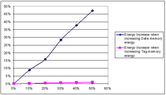
Figure 8. Total Energy when Increasing Data and Cache Memory Energy
The selection of the data memory is then important to optimize the energy of CPU systems. In power critical systems, the use of multiple low power static RAM for data memory can allow a significant power reduction.
5 Conclusion
The simulation of memory hierarchy of CPU systems highlights that dynamic reconfiguration of cache controller is a promising approach to significantly reduce power consumption. Coupled with low power CPU and a judicious choice of the static RAM of the circuit, it will enable to design more complex embedded systems with high battery autonomy.
Our study shows that up to 70% of energy can be saved using a self-adaptive instruction cache. This cache also avoids spending time selecting cache parameters which can be a nightmare for software developers or SOC integrators that are not specialist of cache controllers.
Future way of improvement will be to apply the same methodology to data cache, and to memory hierarchy with 2 or more levels of caches.
6 References
- S. Seagars, « Low power design techniques for microprocessors », IEEE International Solid State Circuits Conference Tutorial
- M. B. Kamble and K. Ghose, “Energy-Efficiency of VLSI Caches: A Comparative Studyâ€, Proceedings of the 10th International Conference on VLSI Design, 1997
- M.D Powell , A. Agarwal , T.N. Vijaykumar, B. Falsafi and K. Roy, “Reducing Set-Associative Cache Energy via Way-prediction and Selective Direct-Mapping†34th International Symposium on Microarchitecture (MICRO), 2001
- S. Musalappa, S. Sundaram and Y.Chu, “A replacement policy to save energy for data cacheâ€, International Symposium on High Performance Computing Systems and Application, 2005
- C. Zhang, F. Wahid, W. Najjar, « A highly configurable cache architecture for embedded systems ». 30th Annual International Symposium on Computer Architecture , 2003
- C. Zhang, F. Vahid and R. Lysecky, « A Self-Tuning Cache Architecture for Embedded Systems » Design, Automation and Test Conference in Europe (DATE), 2004
- C. Lee, M. Potkonjak, W. H. Mangione-Smith, “Mediabench: A tool for evaluating and synthesizing multimedia and communication systems†MICRO 1997
- E. Senn, J. Laurent, N. Julien and E. Martin, « SoftExplorer : estimation of the power and energy consumption for DSP applications », IEEE PATMOS , 2004
- V. Tiwari, S. Malik, A. Wolfe, « Power Analysis of Embedded Sofware: A First Step Towards Software Power Minimization », IEEE Transaction on VLSI Systems , 1994
Olivier Montfort is the manager for the development of the microcontroller solutions at Dolphin Integration. He has over 7 years of experience in the design of embedded memories and microcontrollers.
Olivier holds a master's degree in electrical engineering from ENSEIRB in Bordeaux, France.
