Achim Nohl & Frank Schirrmeister, Synopsys, Inc.
Abstract
This paper will discuss the changing landscape of verification caused by the increased importance of software for the success of chip design projects. With software determining an increasing amount of functionality, design teams are adopting virtual prototypes for early software development. Another use case for virtual prototypes is software driven verification, in which testbenches for verification of the hardware are executed in software running on transaction-level models of processors as part of virtual prototypes. This paper will illustrate the use cases of software for hardware verification across design and verification flows for chip-design.
Introduction
When looking at the complex semiconductor chips to be verified today, they definitely are getting more and more complex. They are developed at smaller technology nodes and, with the declining number of design starts, there are less of them per year. Programmability plays a significant role, both in ASIC and ASSP designs, as users have to deal with more and more processors. In FPGA designs programmability of the hardware itself is complemented by software programmability on processors in the FPGA. In addition, other forms of programmability find more and more adoption, specifically configurable and extendible processors allow the optimized design of application specific subsystems.
Some of the verification drivers depend on the application domains. The International Technology Roadmap for Semiconductors (ITRS) differentiates networking, consumer portable and consumer stationary as separate categories in the SoC domain.
Luckily the concepts of divide and conquer apply for chip design as well and verification can be tackled in several different steps. Honing in on the software aspects, more and more designers not only use embedded software to define functionality, but also use it to verify the surrounding hardware. Such a shift is quite fundamental and has the potential to move the balance from today's verification, which is primarily done using SystemVerilog, to verification using embedded software on the processors (which the design under development likely contains anyway).
Enabling Technologies
The enabling technologies to allow execution of those verification tasks throughout the different project phases can all be categorized as prototyping.
First users apply virtual prototyping before RTL, typically assembling transaction-level models in a virtual prototype together with instruction set simulators (ISSs) of the required processor cores. Virtual prototypes can be very fast in execution when kept at a loosely timed abstraction level. The more accurate users require the models to be, the slower they will run. Later in the design flow, FPGA prototyping offers higher accuracy at higher execution speeds. Finally, once the first chip samples are available, hardware prototypes become viable and later become development kits for software developers.
All of the prototyping techniques offer the ability to validate the chip in the system. In virtual prototypes connections to physically existing interfaces can be modeled, later in FPGA and hardware prototypes real-time wireless or networking interfaces can be connected. The various prototyping techniques serve several purposes. First and foremost, they enable embedded software development before silicon is available, helping to parallelize the hardware and software development threads. They also play some role in architectural and performance analysis, especially for next generation projects. And for verification as described above, they become the execution vehicles to connect hardware and software as early as possible.
Given that each of the prototyping techniques has its own unique advantages and shortcomings, a combination of the different options is recommended to reap all the advantages in a single “Hybrid System Prototype.†Several standards released over the last couple of years, like the OSCI TLM-2.0 APIs and Accelera’s SCE-MI, are bringing the industry closer to the desired capability to mix and match models and execution engines from different vendors for the various prototyping techniques.
Software Driven Verification
As the SoC design cycle progresses, if a virtual prototype was made available early for software development, it can evolve to meet different needs.
There are three main use models of “software driven verificationâ€, which utilize the integration of virtual prototypes with signal level simulation or prototyping at the RT-level.
First, when an RTL block becomes available, it can replace its transaction-level model in the virtual prototype. Software can then be verified on this version of the prototype as a way to validate both hardware and software. Knowing that real system scenarios are used, increases verification confidence. Furthermore, simulation used in verification is faster, given that as much of the system as possible is simulated at the transaction-level.
Second, virtual prototypes can also provide a head start towards RTL verification testbench development and post silicon validation tests by acting as a testbench component running actual system software. The virtual prototype can be used to generate system stimuli to test RTL, and then verify that the virtual prototype and RTL function in the same way. Users can efficiently develop on the TLM model “embedded directed software†tests, which can also be used for system integration testing. As a result productivity of verification test case development increases.
Finally, as portions of the virtual prototype are verified as equivalent to their corresponding RTL, the virtual prototype can become a golden or reference executable specification. As a result users gain a single golden testbench for the transaction-level and the RT level.
Linking Different Abstraction Levels
The transactor interface between virtual prototypes using TLMs and traditional RTL can be written in SystemVerilog to allow the bus functional model to be synthesizable in order to allow co-execution with hardware based environments. Alternatively, the transactor can be written in SystemC and the interface to RTL simulation can be at the signal level.
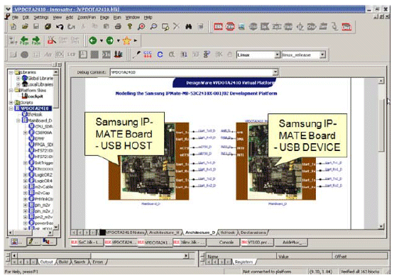
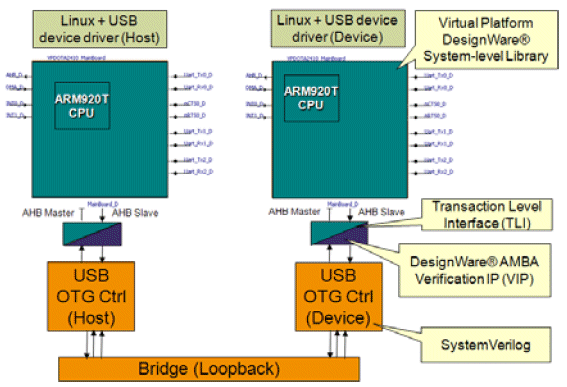
Figure 1 and Figure 2 illustrate an USB OTG example in the Synopsys Innovator virtual prototype development environment and a USB verification environment using TLM processor models and embedded software, respectively. In this particular case the virtual prototype with models representing the USB 3.0 specification has been available well before RTL was developed.
As a result, driver development was largely done at the time RTL became available and several software issues had already been resolved.

Figure 1: Example USB Virtual Prototype
When RTL became available, the virtual prototype became an essential part of the RTL verification environment. Nightly regression tests with TLM virtual prototypes in the loop confirmed that the latest changes in the RTL did not change the behavior at the hardware software interface.

Figure 2: USB Verification environment
Using virtual prototypes for USB OTG driver development resulted in an overall project savings of about 8 weeks. The savings were a combination of early software availability and faster bring-up time of hardware prototypes.
Virtual Prototype Value for Verification
Even when a virtual prototype is not available from the start of the project, virtualization of hardware components can be very important to incrementally increase verification efficiency starting from an RTL verification environment.
Firstly, replacing the RTL representation of on-chip processors in the system with virtual processor models at the transaction level can significantly increase simulation speed, which in turn shortens verification turnaround time. In concrete customer examples we have seen up to 32x speed up of simulation when replacing a single processor model. In the same examples the execution of the virtual prototype itself was about 7000x faster than RTL, while still being functionally and register accurate to allow embedded software development.
Secondly, incorporating software drivers in functional RTL verification to execute real product test cases does not require a complex virtual prototype. Only the appropriate sub-system needs to be modeled and connected to RTL simulation. This can be as easy as adding a transaction-level processor model from a library, connecting it via a simple bus model to the transaction-level model of the peripheral under verification and connecting that to RTL (see Figure 2).
Hybrid Prototypes
Orthogonal to abstraction levels at which hardware can be modeled, it can be prototyped in the context of software either using software simulation or using hardware assisted techniques like FPGA prototyping or emulation.
Different characteristics determine which type of prototype is most applicable to meet specific user requirements:
- Time of Availability: The later prototypes become available in the design flow compared to real silicon, the less their perceived value to hardware/software developers will be.
- Execution Speed: Developers normally ask for the fastest prototypes available. Execution speed almost always is achieved by omitting detail, so it often has to be traded off against accuracy.
- Accuracy: Developers normally ask for the most accurate prototype available. The type of software being developed determines how accurate the development method must be to represent the actual target hardware, ensuring that issues are identified at the hardware/software boundary. However, increased accuracy requires executing more detail, which typically means lower execution speed when done using software simulation.
- Production Cost: The production cost determines how easily a prototype can be replicated for furnishing to software developers. In general, software prototypes are very cost-effective to produce and can be distributed as soon as they are developed. Hardware-based representations, like FPGA prototypes, require hardware availability for each developer, often preventing proliferation to a large number of software developers.
- Bring-up Cost: Any required activity needed to enable a prototype outside of what is absolute necessary to get to silicon can be considered overhead. The bring-up cost for virtual prototypes and FPGA prototypes is often seen as a barrier to their use.
- Debug Insight: The ability to analyze the inside of a design, i.e., being able to access signals, registers and the state of the hardware/software design, is considered crucial. Software simulations expose all available internals and provide the best debug insight.
- Execution Control: During debug, it is important to stop the prototype of the target hardware using assertions in the hardware or breakpoints in the software. In the actual target hardware, this is very difficult – sometimes impossible – to achieve. Software simulations allow the most flexible execution control.
- System Interfaces: It is often important to be able to connect the design under development to real-world interfaces. While FPGA prototypes often execute fast enough to connect directly, development using virtualized interfaces of new standards, e.g., USB 3.0 can be done even before hardware is available.
It is very clear that neither pure software simulation nor hardware_based execution in FPGA prototypes or emulation can meet all user requirements. As a result, the use of hybrid prototypes has recently become more popular.

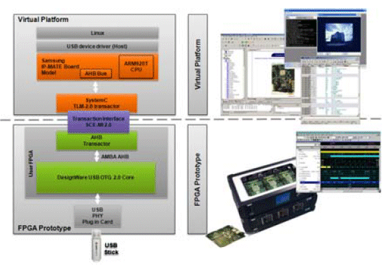
Figure 3: Hybrid prototype
Figure 3 shows such a hybrid prototype, connecting via the standard interface SCE-MI a virtual prototypes executing a ARM based virtual prototype at the transaction-level with a instantiation of a USB interface at the signal level in a FPGA prototype.
Figure 4 shows the speed-up of various combinations of virtual prototypes at the transaction level with signal level representations of the USB interface, executed either in RTL simulation or an FPGA prototype. Compared to real time execution, hybrid ‘System Prototypes’ offer significant speed advantages over pure RTL simulation, therefore enabling higher verification efficiency. In this particular example only the USB interface was kept in the FPGA prototype, leading to a relatively low average transaction size between software simulation and hardware.

Figure 4: Example Speed-up for Hybrid Execution
Using larger transaction sizes at the hardware software interface (like for example complete blocks, slices or even frames) has led in our experience to even more significant speed-up.
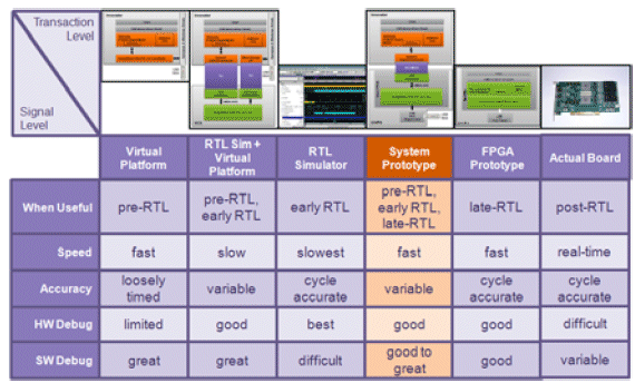
Figure 5 compares six different prototyping techniques and some of their combinations using our example of an ARM-based platform executing Linux connected to a USB 2.0 interface. Depending on the use case, different combinations of TLM and signal-level execution may be preferable. For example:
- For verification the combination of transaction-level models (TLM) with signal-level RTL offers quite an attractive speed-up, and users have started to adopt this combination of mixed-level simulation for increased verification efficiency. This use model is effective even when RTL is not fully verified yet and FPGA prototypes are not yet feasible.
- For software development, system prototypes, i.e. the combination of virtual prototype using TLMs and FPGA prototypes at the signal-level using standard interfaces like SCE-MI, have become an attractive alternative for providing balanced time of availability, speed, accuracy and debug insight for both the hardware and software. This use case is most feasible once RTL is mostly verified and the investment of mapping it into FPGA prototypes is worth the return in higher speed

Figure 5: Pro’s and Con’s of various combinations ot TLM and Signal level execution
Verification Re-use
Software-driven verification of hardware also increases verification-reuse, the application of tesbenches to various phases of the design flow.
With test scenarios defined in software, they can be developed and executed prior to RTL availability using virtual prototypes.
Once RTL becomes available, the same software-driven tests can be applied to RTL, either by connecting TLM models of processors to RTL or by executing on RTL representations of processors.
Once hardware prototypes become available, the same tests can be used yet again, no executing software-driven tests on the FPGA prototype or emulation.
Finally, when the actually silicon comes back from fabrication, the same set of tests can be used again, this time verifying functional correctness of the silicon itself.
Throughout the project flow more detailed tests will be added. They are not necessarily backwards- applicable to tests at higher levels of abstraction.
Summary
Using virtualization of embedded hardware, verification efficiency can be improved both incrementally starting at RTL verification bottom up and top down, starting with virtual prototypes originally intended for early pre-silicon software development.
Incremental verification efficiency is achieved by augmenting traditional RTL simulation with virtualized transaction-level models of processors and peripherals, simply increasing the speed of simulation and directly executing executable reference models as part of the testbench. In top down flows, verification efficiency can be increased by re-use of existing virtual prototypes and their models, which can provide a head start for verification scenario development by simply replacing the RTL under verification until it is available and can become a reference for RTL verification to follow.
Due to varying requirements along the eight categories of time of availability, execution speed, accuracy, production cost, bring-up cost, debug insight, execution control and system interfaces, hybrid prototypes have recently become more popular and offer more flexible trade offs.
Outlook
Software will continue to significantly change the verification landscape. Verification engineers may need to increase their knowledge in traditional software languages like C and C++ as well as in embedded software development techniques to be efficient enough to verify the complex designs the next round of chip designs will bring.
