Mirit Fromovich, Tamar Meshulum (Cadence Design Systems)
Cache-coherent interconnect is a high-risk area
The ARM® AMBA® 4 Coherency Extension (ACE™) specification was officially published more than a year ago. The main driver for the ACE spec is the need to support hardware-managed cache coherency, to satisfy the growing market demand for more performance with less power consumption in today’s multi-core systems-on-chips (SoCs).
Cache-coherent interconnect is the key component in any ACE-based SoC. The interconnect plays the role of the coherency manager; for example, the interconnect needs to snoop the right master, calculate the appropriate response, and make sure it returns the correct data. Some interconnects might include more complex operations , for instance speculative fetches to save time, or utilize a snoop filter to prevent unnecessary accesses to processors that might not be sharing data.
Designing a cache-coherent interconnect that will provide the best performance while implementing the complex capabilities needed for cache coherency is extremely difficult; however, verifying it is even more difficult.
Full UVM Environment for CCI-400
This paper will focus on building a Universal Verification Methodology (UVM) based verification environment that will help you verify an ACE-based interconnect. We will use ARM CoreLinkâ„¢ CCI-400 as the design under test (DUT) in order to demonstrate all the necessary steps that are required to confidently sign off that your design was verified.
CCI-400 is the first Cache Coherent Interconnect developed by ARM. It supports two fully cache coherent ACE compliant masters (like the ARM Cortexâ„¢-A15 and A7) and three I/O Coherent ACE-Lite slaves (like the ARM Maliâ„¢-T604). The ACE-Lite interfaces support distributed virtual memory (DVM) to enable connectivity of memory management units (MMUs). The masters can communicate through the CCI -400 with three ACE-Lite compliant slaves.
Why UVM?
The first question that probably will come up when starting a new verification project is which methodology should the team use? The industry made a decision to align on the UVM methodology due to its many benefits, like ease of use, large system support (scalability), block-to-system vertical reuse, integration-ready components, and more, but how can all of these powerful UVM features help us with the challenges of verifying a cache -coherent interconnect?
In this paper, we review the key UVM components in the CCI-400 verification environment and emphasize how we can leverage the UVM methodology to address the verification challenges the ACE specification brings with it.
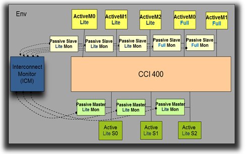
Figure 1: UVM environment for CCI-400
Main Tasks to Verifying ACE-based Cache Coherent Designs
There are three major tasks necessary to verify ACE-based designs. They are:
- Mimic all ACE-supported scenarios to cover the full protocol space
- Ensuring compliance with the ACE specification and coherency in the system
- At the Interface level
- At the Interconnect level
- Measure coverage in order to reach verification completeness
Task 1 – Active agents to mimic the memory and processor in the system
In our UVM environment (uvm_env), we will instantiate master and slave active agents, which drive data and respond to activity on the bus. Each agent needs to be configured to represent the corresponding component that will be integrated later in the RTL. UVM configuration objects encapsulate all the necessary information the agent needs to accurately mimic your real processor in the system.
Since a major challenge in verifying an ACE-based system is the tremendous size of the verification space, reducing the space to match your own design will help ease this challenge. The trivial configuration options would be things like protocol flavor (AXI4/ACE/ACE-Lite) or cache line size. Important ones would be things like whether the system supports all legal states or just those expected, SharedDirty (the A15 does not), snoop filter, and ACE-Lite DVM (like in the CCI-400 case).
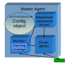
Figure 2: Agent configuration
1.1 Atomic ACE transactions on a master
The driver is responsible for getting a legal transaction and sending it on the bus. To create this transaction in ACE, unlike in AMBA 3, the protocol constraints are not enough. You must take into consideration the cache line state. Clearly, this indicates the need for a cache model in your master agent. There, additional constraints are required. These constraints will ensure for example that WriteBack burst will not be generated for a CLEAN cache line.
1.2 Store/Load transaction on a master
Many times when you define your scenario you would like to think at a higher level. Instead of thinking about all the different types of transactions (like ReadShared, CleanUnique, MakeUnique, WriteBack etc.), you prefer to think about Load and Store operations. Load and Store operations might break down into other low-level transaction depends on the cache state but it’s best to create a high-level sequence that hides the details. The example in Figure 3 is focused on one permutation of a high-level store sequence from the low-level sequences.
First, we check the cache line state. Here we review the section when the cache is invalid. According to the given store data size, we define if this is a partial cache store or not. If this is indeed a partial cache line store, we request other masters to remove their copies. We then obtain a unique copy by sending a ReadUnique, and then perform the store. If this is a full cache line store, we request other masters to remove their copies by sending MakeUnique, and then we perform the store.
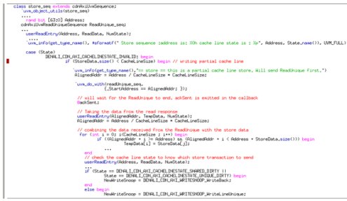
Figure 3: Building a high-level store sequence from the low-level sequences
1.3 Multiple masters/slaves scenario -Virtual Sequence
Until now we have discussed only sequences on a single interface. But usually when you try to define an interesting scenario in ACE, you want to coordinate activity between the multiple masters in the environment. Do this in a UVM environment with a virtual sequence that is defined in your uvm_env and is connected to all of the sequencers in each of the active agents.
Let’s review a sample virtual sequence in CCI-400.
The scenario description:
- M3 has cache in SC
- M4 has cache in I
- M4 sends ReadShared
What will happen:
1. M4 sends ReadShared transaction
2. CCI does speculative fetch to S0 + ReadShared SNOOP to M3 (Table C5-1)
3. M3 sends a snoop response DATA_TRANSFER, NO_PASS_DIRTY, IS_SHARED (Table C5-8)
4. M3 doesn’t change its cache line state
5. M4 receives a response with NO_PASS_DIRTY and IS_SHARED (Table C4-9 with initial state Invalid and “10â€)
6. M4 changes cache line state I Ã SC
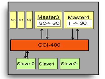
Figure 4: Virtual sequence example in CCI-400
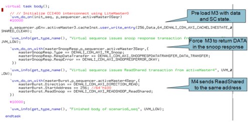
Figure 5: Virtual sequence code example
Task 2: Coherency Checking- ensuring ACE specification compliance and system coherence
Each master and slave must be verified individually to ensure it complies with the specification, but this is not enough. The verification IP (VIP) must be teamed with a monitor that watches all the traffic on the interconnect. This is necessary to ensure coherency of the full system. An ACE verification solution needs to perform two key tasks:
- Ensure that each individual component (e.g. processors, memory) behaves correctly
- Monitor the interconnect to ensure that communication between all blocks is accurate and in compliance with the ACE specification.
Item 1 is achieved by the VIP’s master and slave agents. The VIP can be active and replace the RTL block, and once the user has integrated the block RTL with the interconnect DUT, the VIP will move to passive mode and monitor the bus interface to ensure protocol compliance. On top of that, each master agent also must hold a cache model that will serve as a mirror image of the processor cache. It does so by monitoring transfers on the bus.
To enable Item 2, verifying the system coherency, a separate interconnect monitor (ICM) is also required. The interconnect monitor is the only component that has a view of several interfaces. Without such an interconnect monitor, it is impossible to ensure full system coherency. This monitor also checks data integrity and correctness of the interconnect itself to be sure it is passing data correctly and is behaving in compliance with the ACE specification.
For example, only the interconnect monitor can verify that a transaction from a master reaches all the needed snooped masters in the corresponding coherency domain, and that if there was a speculative fetch, the data and response was taken from the right source(s). It can also ensure the data was not returned before all snoop partners have responded, as shown in figure 7.
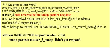
Figure 7: An interconnect monitor error example
If the interconnect DUT has a built-in snoop filter, the interconnect monitor can verify that if a snoop was sent to an address not in the cache of the master, this master will not be snooped. Another example is in the case of barriers, where the interconnect monitor system view can check for the propagation of a barrier together with barrier respecting bursts.
The steps to integrate an interconnect monitor are as follows:
- Configure your interconnect monitor: number of input/output, memory mapping, setting domains (see Figure 8)
- As interconnect monitor is a meta monitor; you will need to connect it to the VIP monitor
- Configure the interconnect monitor to match the DUT definitions (example of ID and snoop conversion)

Figure 8: Interconnect monitor configuration
Since interconnect behaviors are often design specific, the interconnect monitor will need to be flexible and support the verification of these additional rules. One such example is to enable changing the default snoop conversion tables of the ACE spec and altering it to DUT-specific conversion tables.
If the processor (e.g. A15 ) do not support SharedDirty states, the interconnect needs to convert ReadNotSharedDirty to ReadClean. Figure 9 shows a code example of how to do that. The interconnect monitor will verify this design-specific functionality.

Figure9: Snoop conversion (code example)
Task 3: UVM Monitor – coverage model
The huge state space associated with ACE based designs presents a key verification challenge. Simply defining all the complex scenarios requires major investment in itself. Yet, this is not sufficient. The ACE verification solution must enable you to also measure and ensure completeness of the verification space.
Further reducing risk, in this model, coverage is used as the metric for determining verification completeness. Therefore, it is imperative that the VIP provides the complete coverage map based on the ACE specification. The next step is defining the interesting crosses, like the cache state and the transaction type. The tricky part in defining the coverage is to make sure you remove the crosses that are not legal in the specification otherwise the analysis of the coverage result can become a real nightmare.

Figure 10: SV coverage definition examples

Figure 12: SV coverage results
Summary
To recap, the three major elements needed for an ACE verification solution are:
- Stimulus: Constrained-random stimulus is required to mimic all possible scenarios. The ability to define high-level scenarios and also to coordinate between the multiple agents is necessary for an ACE-based SoC. To achieve this, we discussed the following tools: configuration properties to reduce the verification space, constraints to generate a correct data item, cache models to provide the cache state to the constraints, and a virtual sequence to coordinate the different masters.
- Checks: Each interface requires complete protocol compliance checking to ensure protocol compliance at the interface level. In addition, we have seen that system coherency checks at the interconnect level are necessary, in order to verify the system coherency.
- Coverage: Reduce the huge ACE coverage space by developing and using a coverage map that matches your design and the accurate specification of all legal cores.
The Universal Verification Methodology (UVM)—with its built-in sequence and virtual sequence, coverage, scalability and reuse—provides a very powerful infrastructure for achieving your goal of verifying an ACE-based system.
About The Authors
 Mirit Fromovich, Verification IP Solutions Architect at Cadence Design Systems, leads the worldwide deployment of AMBA verification IP. Mirit is an expert in the application of verification IP and advanced verification techniques and technologies having worked in the field over 10 years. Mirit holds a BSC in software engineering and mathematics from the Bar-Ilan Institute of Technology.
Tamar Meshulum, Interconnect R&D manager at Cadence Design Systems, leads the interconnect verification product development. Ms. Meshulum is an expert in advanced verification techniques and technologies having worked in the field over 10 years. Tamar holds a BSC in engineering from Tel Aviv University
