Shiva Belwal, Harkaran Singh, Abhishek Mahajan, Freescale Semiconductor
Engineering Change Order or ECO is the process of inserting logic directly into the gate level netlist corresponding to a change that occurs in the rtl due to design error fixes or a change request from the customer. ECO is preferred as they save time and money in comparison to a full chip re-spin. Some of these ECOs come very late in the design cycle, some of them have high level of complexity involved and at such times the need for an automated tool becomes a necessity.
The idea proposed in the paper addresses this very issue. With this idea even complex ECOs can be implemented automatically in lesser turnaround time.
With the increasing logic size and complexity in SOC’s as well as development of complex techniques of logic optimization during synthesis, compounded with the absence of any stable ECO flow/ tool it is becoming increasingly difficult to implement ECOs in the design.
Although there are tools in the market that support ECO implementation but they are mostly unstable and inconsistent. The major issues seen in the existing tools are:
- Huge runtime: The existing tool flow requires full SOC synthesis which could consume 2-3 days depending on the design size.
- Large Patch size: Generally the patch generated by these tools is larger than required.
- Setup Time: The setup generation time for ECO tool also becomes a limitation for using it in most of the cases.
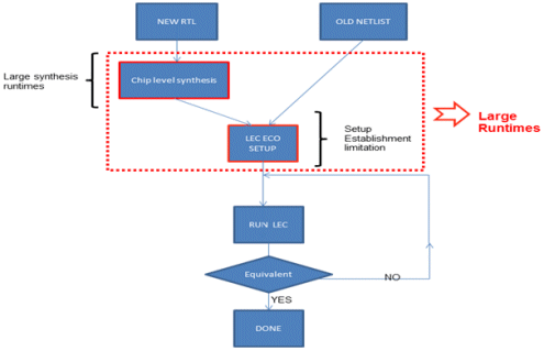
Flow used by existing tools in the industry:

FLOW CHART 1
As can be seen from Flow-chart 1, the existing process requires a full chip synthesis corresponding to the new RTL. The approach also does not account for boundary optimization that occurs during synthesis, the patch that is generated is usually larger than required. The main disadvantage of this flow is therefore the huge runtime that is required for the synthesis of the new RTL as well as for setup generation. Even after spending all this time on ECO implementation it is not ensured that the resulting ECOed netlist will be logically equivalent with the corresponding RTL.
If the existing flow fails then the synthesis engineer is left with the only option of manually implementing the ECOs. Now this has its own challenges. It is difficult and very time consuming to implement a large number of ECOs manually. Also the need to implement a single ECO on multiple DBs involves a lot of man hours and efforts. This once again calls for the need of a new and faster way of ECO implementation with less manual intervention.
All the above mentioned factors lead to the development of the idea discussed in this paper.
The idea provides a fast and automated way to implement complex ECOs. The turn-around time of the flow is less, so ECOS that we encounter very late in Design cycle can also be accommodated.
- The proposed flow will significantly reduce manual intervention while implementing the ECO.
- The flow works on a Module level so the runtime for the logic generation and ECO implementation is very less as compared to tools in the market that adopt a flat approach leading to a huge runtime.
Most importantly it takes care of boundary optimization the very reason why across industry tools use flat approach for ECO implementation.
- The flow also supports user defined optimization levels for efficient patch optimization.
- For Metal ECOs the flow can automatically identify the spare cells and implement the ECO with the available set provided a sufficient number of spare cells are available else a warning for the same will be flagged to the user and the tool will exit without making any changes to the design.
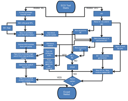
Flow proposed in this paper:

FLOW CHART 2
The Flow-chart 2 indicates that the proposed idea involves block-level synthesis. This significantly reduces the run-time. This approach also involves identification of internal nodes to optimize patch efficiently. Takes care of boundary optimization thereby reducing the chance of false non-equivalences and also optimizes the patch size.
Methodology:
The flow requires a lot of steps happening simultaneously between Synthesis tool and Formal Verification Tool (can be referred to as Logic Equivalence Checker or LEC).
- Using Synthesis Tool we generate a new gate level netlist using boundary optimization report and new RTL. At the same time we extract the block level netlist of the module in which eco needs to be implemented.
- Simultaneously, on LEC tool shell we perform logical equivalence check between old and new RTL and once the new netlist is available from Synthesis Tool, the check between new and old netlist is performed.
- The number of non-equivalences should be same in both cases.
- Once that is ensured, logic corresponding to the ECO is extracted from new block level netlist and inserted in to original netlist (block-level).
- Logical Equivalence check is run between new block-level RTL and modified block-level netlist.
- Once Logical equivalence check is clean, the modified block is plugged into the top level netlist. This is the final formally verified logically equivalent ECOed netlist. The flow also supports multiple level of optimization which can be used based on design stage (base or metal eco).
- For metal ecos, tool identifies all the cells whose output is floating and tries to synthesize the eco logic using those cells only.
The Flow chart 3 clearly outlines the flow just described.

Flow chart 3
Conclusion:
To conclude, the above mentioned flow is not iterative and consumes very less runtime as it works on module level. Also, the flow identifies non-equivalences and at same time implements the change corresponding to non equivalences in the design.
