By Deepak Mahajan and Mohammad Kamil (Freescale India Pvt Ltd)
In this modern era, the market of hand-held mobile devices (like: tablets, smart-phones, cameras, GPS, PDA, etc) have grown by leaps and bounds, prompted by the rapid enhancement in technology, software, hardware, and size (reduction). All these state-of-art devices are powered mainly by batteries, and have over the years adding more features like touch based screen, wider display and run variety of applications connected to internet. All of this leads to more power consumption .Battery size and capacity has not been able to scale at the rate of the power demand and due to which it requires to be charged very often. So you still have to carry around chargers and have a number of wires you have to grapple with frequently, making you feel as if you are still in stone-age even with a futuristic looking gadget in hand. For these reasons, scientists are working on to develop methods to transmit power wirelessly that could cut the clutter and the hassle for carrying so many add-ons to a device. It may sound futuristic but not unrealistic.
Wireless transmission of energy is actually very common in world in the form of Electromagnetic Waves such as Radio Waves, Microwave, etc, which are used to in Mobile Communication, Satellite, Radio, TV, etc. These waves spread in all directions from the transmitter until they reach antennae that are tuned to their frequency and hence, only a small portion of energy actually reaches the receiver. If this method is used for transferring electrical energy then, it would be very inefficient. Before the advent of microprocessors, the concept was marred with inefficiencies and lack of control. It was also a concern from the view of safety and other issues.
The majority of the wireless charging techniques today, use inductive coupling for the transmission of electricity. Although there are other methods to transmit electricity wirelessly using laser-photodiode, microwave beam, etc but these are not within the scope of this article.
Basic Principle
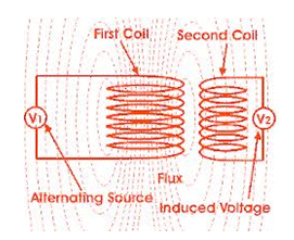
Inductive coupling (Fig. 1) is being used in a myriad of electrical machines. It uses the magnetic field that is produced with any moving current. It is basically, transformer principle in which electrical energy is transferred between two inductive coils by making them magnetically coupled. This is governed by the basic laws of electromagnetism given by Faraday. The energy induced in the receiver is alternating in nature and needs to be transformed to DC, as the mobile devices work on DC.
Electrical devices do not prefer to couple magnetic field over air because air has low permeability and hence less efficient. But for mobile applications air is still a preferred medium as using high permeability core will make the device heavy. Using resonance we can effectively increase the amount of energy that can be transferred over air for small distances.
Wireless charging is further complicated by the fact that this requires a good communication and control over the quantity and quality of the energy that is being transmitted and received. For this we require complex and highly advanced electronic circuitry. Here arose the need for building a standard for transmitting energy wirelessly.

Fig. 1
Inductive Electrical Power Transfer standard
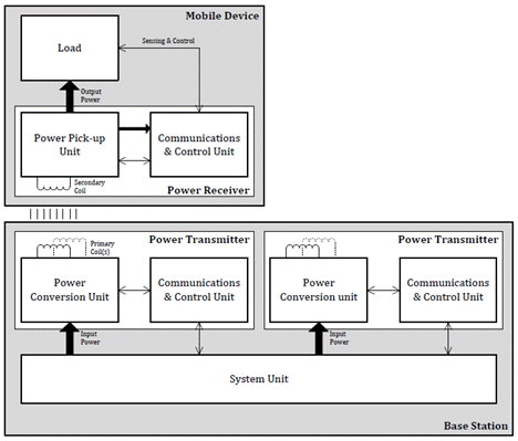
Wireless Power Consortium is an open membership organization with over 100 companies as members working towards the creation and development of single interoperable universal standard for inductive charging technology. Qi (pronounced "Chee") is the interface standard being developed by this consortium for inductive electrical power transfer over distances of up to 4 cm (1.6 inches). The Qi system (Fig. 2) comprises a power transmission pad and a compatible receiver in a portable device. To use the system, the mobile device is placed on top of the power transmission pad, which charges it via electromagnetic induction.

Fig. 2 Qi Standard system
Qi system use inductive coupling between two planar coils to transfer power from the power transmitter to the power receiver. Regulation of the output voltage is provided by a digital control loop where the power receiver communicates with the power transmitter and requests more or less power. Communication is unidirectional from the power receiver to the power transmitter via backscatter modulation. In backscatter modulation, the power-receiver coil is loaded, changing the current draw at the power transmitter. These current changes are monitored and demodulated into the information required for the two devices to work together.
Mobile device manufacturers that are working with the standard include HTC, Huawei, LG Electronics, Motorola Mobility, Nokia, Samsung, and Sony.
Though the current standard is just 5W for smart-phones (1A@5V) obviously charging tablets and larger devices is something coming down the road for the Wireless Power Consortium. So 10W solutions are in line for these devices. At present, inductive chargers achieve around 70% efficiency.
Qi standard compliant Freescale solution

Fig. 3
How it works
Transmitter:
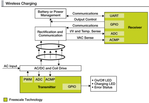
The power transmitter consists of inverter circuit, primary coil and Control and Communication unit. The inverter supplies the controlled AC power to the primary coil, and this control is regulated by the Control and Communication unit. This unit is basically a microprocessor chip. It senses the Voltage/Current in the primary coil and adjusts the parameters of the inverter to have a required amount of the same. The microprocessor unit consists of PWM (pulse width modulator), ADC (analog to digital convertor), ACMP (Comparator), GPIO (for communication with external world). ADC, comparator and PWM makes a feedback loop that controls the current supplied to the transmitter coil. This controls the magnetic field that will be mutually induced in the receiver coil and eventually the voltage in the receiver circuitry. The ADC takes the input from the coil in the form of voltage/current and adjusts the PWM output for the current supplied to the coil. There is also a comparator which compares the voltage/current input from the coil and compares it with the reference set as per the receiver requirements. After the comparison it takes immediate action in case of any fault to protect the circuitry from damage. Also there is a feedback path from receiver to transmitter to adjust the flux in the coils, this feedback happens by superimposition of the communication signals on the power signals itself. This feedback is also important to save power, in cases where there is no receiver placed on the transmitter platform, there is no need of flux in the coils so the transmitter circuit will go in low power mode.
There are techniques to detect if there is receiver present or not:
- By the touch sensing: If there is receiver placed then the signals will be sent to the transmitter to supply current to the coil for generating required voltage in the receiver.
- Acknowledgement from receiver: The transmitter sends continuous ping to the receiver waiting for the acknowledgement from the communication channel, as soon as the receiver is placed the transmitter gets an acknowledgement and supplies current to the coil.
Receiver:
At the receiver side there is a rectification unit with takes the ac component from the coils and converts it to dc and supplies to the battery circuit of the receiver for charging. The analog component from the coils also goes to the microprocessor for comparing it with the reference required and providing feedback to the transmitter to adjust the transmitter current/voltage. Receiver Microprocessor unit consists of ADC, ACMP, UART. ADC takes the voltage and current from the receiver coil and converts it into digital format and then further processed by the Microprocessor for proper actions. The same voltage goes as input to the ACMP which compares it with the reference (set as per required voltage by receiver) and takes immediate action in case of any fault. Microprocessor can turn of the receiver circuit in case the comparator output shows fault behavior (voltage not in range). The receiver also sends the feedback signals back to transmitter through communication channel to adjust the current in the coils.
Wireless Charging Applications:
There can be a lot number of areas where It can be used, listed few of them:
- Offices
- Vehicles
- Café’s
- Libraries
- Airports
References
http://en.wikipedia.org/wiki/Qi_(inductive_power_standard)
http://www.freescale.com/webapp/sps/site/application.jsp?code=APLWIRCHA&tid=vanwirelesscharging
http://en.wikipedia.org/wiki/Inductive_charging
http://www.anandtech.com/show/5412/ti-wireless-charging-new-chipsets-and-10w-charging-for-tablets
