Rich Edelman, Alain Gonier (Mentor Graphics)
Abstract
SystemVerilog [1] UVM [2] sequences [4][5] are a powerful way to model stimulus and response for functional verification. Unfortunately using SystemVerilog UVM sequences can require an extensive background in SystemVerilog, the UVM and object oriented programming. This paper explains a collection of techniques to allow the power of sequences with familiarity and simplicity of calling tasks.
Background
Using SystemVerilog UVM, sequences can be built to provide stimulus and checking capabilities for tests and verification IP. These sequences allow for powerful control over randomization and generation of scenarios for test stimulus.
Verification IP is used to simplify the verification task. For example, an AMBA® AXI [3] verification IP can be used to generate AXI traffic, or send simple burst commands, or even just one transfer on a single channel. Today’s verification IP is being packaged with UVM sequences as a way to control the IP.
Providing sequences as a way to control the Verification IP allows full flexibility for powerful stimulus generation. Unfortunately using a sequence interface for Verification IP may require knowledge about SystemVerilog, randomization, constraints, object-oriented programming and detailed UVM. Many verification teams lack this knowledge.
This knowledge gap can be filled with a simple task based interface around the UVM sequence-based verification IP. The remainder of this paper will describe such an interface, and provide an example using it. These techniques can be adopted for any SystemVerilog UVM sequence interface.
Verilog Tasks
The Verilog language has contained tasks since its beginning. A task is a collection of statements that perform some common function. Furthermore, a task is different than a Verilog function in that it can consume time.
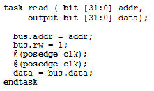
The task above is named ‘read’, and takes two arguments. The first argument, ‘addr’, is an input to the task. The second argument, ‘data’, is an output from the task. The task body performs the desired functionality – in this case, performing a read on a bus by placing the address on the bus, setting the bus ‘rw’ signal, and then waiting for two clocks. After the second clock, the data is retrieved form the bus and assigned to the data return argument. Then the task returns.
Sequences
A sequence is really just a fancy name for a function or task call [4]. It is called a sequence because its main use is to generate a sequence of transactions. The sequence could be from 1 to N transactions, or could be no transactions. A transaction is just an abstraction of some communication. For example WRITE(34, 20) is a transaction that tells a component to write address 34 with the value 20.
A simple sequence might iterate through an address range, first writing, then reading and checking the value read against the value written. Such a sequence is listed below as ‘rw_sequence’.
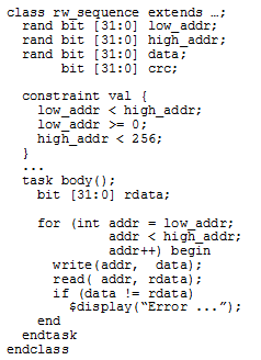
The sequence above is a class definition named ‘rw_sequence’ which contains 3 member variables, ‘low_addr’, ‘high_addr’ and ‘data’. They are each random a variable, and may have constraints such as the ‘val’ constraint which controls the values of low_addr and high_addr. Low_addr must be 0 or greater. High_addr must be greater than low_addr, and must be less than 256.
The ‘body’ task is simple. It goes through each address between low_addr and high_addr, issuing a write, then a read followed by a check.
Sequence / Task Equivalence
Given the sequence above, you could imagine a task named ‘rw’ implemented as
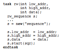
This task first constructs a new sequence and then fills in the sequence member variables with the values from the task arguments. Then the task calls ‘s.start(sqr)’. Calling start means the sequence will execute. The body task of the sequence will be called.
This task is the simple gasket used to fill the gap between the task based world and the sequence based world.
Not every verification engineer will need to write tasks like this. A verification IP developer may include this layer with the UVM sequences for ease of use, or a testbench architect may create this layer for internal use on the verification team.
Simple Task with Arguments
A simple task with arguments was demonstrated above in the read task and the rw task. Besides input arguments and output arguments, a task can also have ref arguments. Input arguments are passed in to (copied into) the task. Output arguments are passed out (copied out) of the task. These arguments are pass-by-value. The task gets a copy of the input value and returns a copy for the outputs. The potential exists for a lot of copied data.
SystemVerilog also allows task arguments to be references (ref arguments). No copy is made, and a value can be passed in and a changed value can be returned. Ref arguments are pass-by-reference. Ref arguments are convenient for arguments that have an input value which will be modified or for arguments that are large.
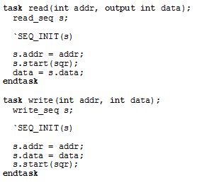
Once the task arguments have their types and input/output/ref decided, then it is a simple matter of transferring the data from task arguments to class member variables. The task input arguments should be copied to the sequence ‘rand’ variables. After the sequence has been run (after the sequence start returns), the output class member variables are assigned to the task output variables (see the read task below for an output variable).
A simple read task and a write task, invoking the read_seq sequence and write_seq sequence respectively.
In the code block below, the task ‘rw’ is being called with 4 arguments. The ‘rw’ task has been changed to have an output argument named ‘crc’. The crc is returned, and a sum is created as the loop progresses.
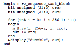
Sequence Member Variables.
In a sequence, member variables are the inputs and outputs. A variable marked ‘rand’ is thought of as an input variable. It is a variable that can be randomized and take different values. A variable not marked ‘rand’ is thought of as an output variable. It is the result or value of the operation.
When the number of arguments gets large, or the data types of the arguments get large (such as large array of data), it can be useful to use the sequence directly, and not even have the task. The sequence handle can be constructed, randomized and started by the inline test code.
Using A Sequence Handle Directly
A task call is a convenient way to hide the complexities of the sequence, but in addition to simplifying, it also removes much of the power of sequences. A sequence handle can be used directly – accessing the fields of the sequence as needed.
Declare the sequence ‘s’. Construct the sequence ‘s’. Assign class member variables in ‘s’ (low_addr and high_addr). Start the sequence on the proper sequencer. Retrieve any calculated or output value (crc in this case).
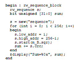
Randomizing a sequence handle
A task with arguments provides a way to interface to a sequence with member variables but misses out on one of the most powerful parts of sequences – randomization of member variables.
In the code block below, the sequence ‘s’ is declared. Sequence ‘s’ is constructed and then randomized each time through the for loop. After randomization the sequence is started on the proper sequencer.
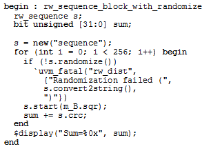
The Container Module
Tasks provide a familiar way to interact with UVM sequences. There are some minor details that must be managed. The sequence “runs on†a sequencer. A sequencer is part of the design of the UVM Agent based verification IP.
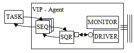
Figure 1 - Task interacting with VIP Agent
When we say a sequence runs on a sequencer, we mean that under normal circumstances a sequence requests access to a driver by allowing the sequencer to arbitrate requests. For the task to send requests and get responses from the driver, it also needs to have a sequencer.
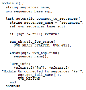
The task based simplification needs to have a sequencer handle available. This is most easy by using a container like a module. The module ‘m’ below is such a module.
Module m contains a sequencer name and a sequencer handle. The handle will be filled in based on a call to the UVM ‘find’ command. Before the find command (or any part of the UVM ) can be used, we must be sure what state it is in. We synchronize with the UVM using the ‘wait_for_state’ call to wait until the UVM phasing engine enters the run_phase PHASE_STARTED state. Once it has entered that state we are guaranteed that the components are built and ready to use.
We instantiate this module like any other Verilog module, and then we use the UVM find command to find the proper sequencer, and save a handle to it. Now we can say that this module instance is “connected to†or can make requests of the sequencer and in turn can send transactions to the driver.
The module m contains tasks which act as the gasket to the sequences. The tasks ‘read’ and ‘write’ below build a sequence of the appropriate type (read_seq or write_seq) by calling new. Before we use the start call to run the sequence, we synchronize with the UVM to make sure we are in a known state (run_phase::UVM_PHASE_STARTED).
After the sequence is constructed we copy the task arguments into the sequence class member variables.
Then we call s.start(sqr) which causes the sequence named ‘s’ to be run on the sequencer ‘sqr’. Internal UVM plumbing will cause the sequence ‘body’ routine to be called. The body task is the definition of this sequence. The body task is the behavior.
After ‘start’ returns the sequence has completed execution. At that time we can copy the data value from the sequence class member variable into the output argument ‘data’.
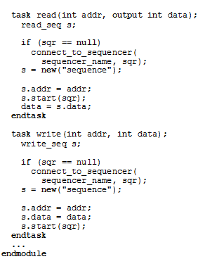
The container module could be a SystemVerilog interface or class. It doesn’t matter as long as a container is used to help manage things like the sequencer name and handle, and is used to contain the tasks that are valid with this particular interface and collection of sequences.
Using the Container Module
The container module is instantiated just like any Verilog module. In the code below we have two instances of module m (m_A and m_B). The initial block begins by setting the sequencer_name that each module instance should connect to. One module connects to one interface.
Synchronizing with UVM Phasing
Using wait_for_state, the code synchronizes with the UVM run_phase.
Once synchronized, the first thing that happens in the testbench is that an objection is raised. This is a UVM mechanism to end simulation. Simulation will end when no objections are raised. So the method is raise the objection, do the tests, lower the objection, wait for all objections to end, exit simulation.
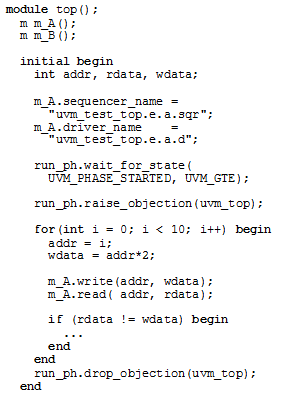
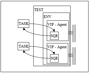
Figure 2 - VIP Agent based Test
The sequencer is just an arbiter which arbitrates multiple sequences which desire access to the driver. The sequencer can be retrieved in many ways, the example below uses find.
Summary
SystemVerilog UVM sequences are very powerful, but are sometimes more complex than users are comfortable with. Using a task based interface can fill the complexity gap by providing a more familiar use model while at the same time preserving the power of sequences. Both the task based interface and sequences can be used alongside each other.
References
[1] SystemVerilog LRM. IEEE 1800-2009.
[3] AMBA ® AXI Protocol Specification, Version 2.0
[4] Edelman, Rich, “Sequences in SystemVerilogâ€, DVCON 2008
[5] Edelman, Rose, Meyer, Ardeishar, Polychronopoulos, “You Are In a Maze of Twisty Little Sequences, All Alike – or Layering Sequences for Stimulus Abstractionâ€, DVCON 2010
Appendix
Contact the authors for full source.
