By Emmanuel VAUMORIN, Didier MAUUARY, Guillaume GODETBAR, Simplice DJOKO-DJOKO, Saddek BENSALEM, Julien MOTTIN, Frédéric PETROT, Matthieu PFEIFFER, Christian FABRE, Nicolas FOURNEL
ABSTRACT
When implementing new embedded applications, industrial companies are facing new challenges: these applications are very complex to program (between 5 and 10 million lines of code are common) and require handling of several possibly heterogeneous models and languages. Integration choices are wide-ranging, from functions hard-coded in hardware IP to embedded software for multi-core clusters. Additionally integration must take into account at the same time several kinds of constraints: processing power, memories, power budget limitation, etc.
Thus, new methodologies are required to keep the productivity at an acceptable level, to support the complexity of designs and to ensure the integration of hardware and software design flow. This paper presents how the project ACOSE provides solutions to solve the following issues:
- Managing application requirements which are transverse: functionality, performances, consumption, security, etc.
- Hardware-Software partitioning
- Safety constraints requiring rigorous design
- Choice and configuration of the target hardware platform
- Design and deployment issues within industrial contexts
- Application code generation for the target platform
- Simulation, co-simulation, virtual prototyping
- Requirement traceability and specifications impact analysis
- Performance analysis
KEYWORDS
Domains: EDA, complex embedded system engineering, heterogeneous design, product life management, IP-XACT (IEEE 1685-2009), SystemC, software components, system level design (ESL), SysML, MARTE, UML, system simulation, low power management, wide sensor network, model transformation.
1. INTRODUCTION
ACOSE develops a rigorous system design framework that allows for several levels of abstraction of the system under design. These levels can cover models of the application alone, of the platform alone or system models that encompass the application on its platform both altogether.
ACOSE targets hard issues like complexity, separation of communication and computation, quality of service, correctness by construction by offering model and component-based designs while addressing key industrial concerns like legacy integration, optimal power efficiency and integrated development traceability. This will help SoC (System-on-Chip) and CPS (Cyber-Physical Systems) integrators to put in place development strategies that cover the whole development and life cycle of a system.
2. INDUSTRIAL REQUIREMENTS AND PROBLEM STATEMENT: Distributed sensors network
In this part we describe how the industrial use case, a wireless sensor network proposed by CYBERIO, is a good candidate to illustrate how the reported industrial issues are addressed by ACOSE.
Designing networks of sensors, or network of connected objects, is without doubt one of the most challenging technical issues of the coming decade. Networks of sensors improve the ability to get information about global systems such as national and international size power grid, mass social behavior, economic and ecological systems. Networks of sensor are particularly relevant in “cyber physical systems”, a new research paradigm involving large network of sensors, actuators and distributed computing platform.
Designing a good sensor network application involves an unprecedented number of technical challenges. First, the number of hardware units involved in sensor network application that dramatically enhanced the risk of
- hardware/software maladaptation,
- bad unit level energy consuming optimization that turn into high global energy budget,
- facing the heterogeneity of many different hardware platform,
- data flow / network bandwidth maladaptation
Secondly, the massive size of the target application implies the following needs:
- debugging the application at the network level,
- updating the application at the network level,
- configuring the application at the network level,
The requirements generally needed for sensor network applications are the following:
- Real-time requirements: the distributed application should respond within a fixed amount a time,
- Energy requirements: the distributed application should consume as low energy as possible and be autonomous as much as possible,
- Entropy requirements: the distributed sensor application should be built with a quantitative measure of the information to be collected
Goals of the ACOSE project versus the sensor network challenges:
- propose a single tool for designing/programming/testing applications at the scale of the hardware infrastructure,
- propose a strategy for developing cooperation between sensor networks,
- Facing the problem of heterogeneous board/network/cloud hardware. A typical example is to develop a sensor network with existing pools of smartphone/tablet PC hardware. In such a case, How to guaranty the requirements with many different hardware properties?
The complexity of the design problem is illustrated in the figure below:
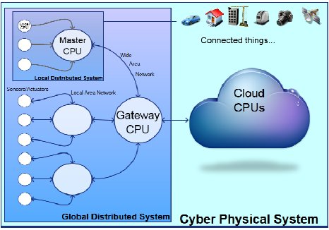
Figure 1: Complexity of the design problem
Sensor hardware, local bus physical type, master CPU of the LAN network, wide network area physical type, gateway CPU, and cloud infrastructure may all impact the requirements of the application. So they should be integrated as soon as possible in the design flow.
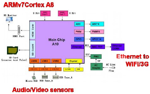
At the sensor level, a typical board is depicted at the figure below:
Figure 2: typical board at the sensor level
The audio peripheral hardware, the bus between audio chip and processor (Nova A9500), the bus between processor and Wi-Fi chip, as well as the Wi-Fi specifications has to be accounted for. In order to give a clear and concrete demonstration of the work, we intend to develop two prototypes:
- A “real scale” network of ultrasound sensors deployed through the city of Grenoble and through surrounding suburban cities,
- An innovative augmented reality device that enables to see sounds in the dark where no light is available.
The aim of the demonstrators is to fulfill a technical proof of concept as well as to conduct a premium experiment in measuring the biodiversity of bat species at an urban scale, which was never tempted before. Indeed, bat species living in the city of Grenoble use ultrasound to eco-locate, capture their preys and also to communicate. So, ultrasounds sensors are a good strategy to detect and monitor the bat presence in a given area.
The augmented reality prototype is an innovative device that uses the synchronization between acoustic sensors to locate the sound source and visualize it on a screen. It leverages the acoustic camera principle.
3.INNOVATIVE FLOW
3.1 - Description of ACOSE’s flow
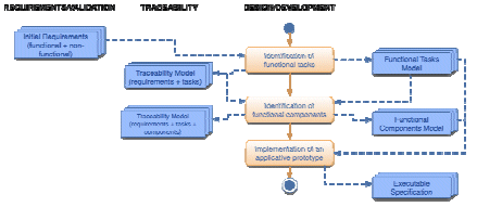
3.1.1-Specification phase
The specification phase aims at the description of the nominal behavior of the application, independently from the future partitioning of functional tasks between hardware and software.
This phase also aims at the description of a formal model corresponding to a high level executable specification, which may be used further as a support for validation.
Figure 3 : Specification phase
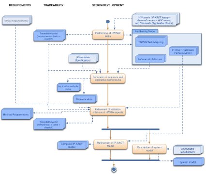
3.1.2-Design phase
Design phase is initiated by the definition of a proposal for partitioning the functional tasks between hardware and software. It is then followed by the refinement of this choice under structural and behavioral models
Figure 4 : Design phase
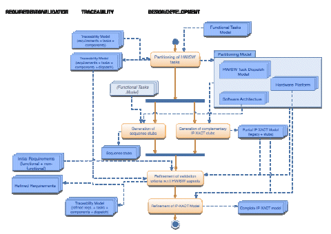
3.1.3 - Implementation phase
This last phase is made of two kinds of activities: automated code generation and refinement of generated code in order to evaluate as soon as possible the pertinence of implementation in regards with behavioral executable model described in the design phase.
Figure 5 : Implementation phase
3.2 - Fragmented documentation assembly and traceability management
3.2.1 - Interdependencies between abstraction levels and domains
Similarly to general design flows of embedded systems, the diversity of models implied in the ACOSE flow and the inherent documentation of the system involve a crucial need for traceability of information. An integral requirements-driven design flow, consisting of starting from a formal model at the system level that is refined though several iterations towards implementation, brings up necessarily needs of enhanced traceability.
As depicted in the previous section, the design of a complex system implies elaborating and handling formalisms at diverse levels of abstraction of the flow (specification, design, and implementation). Obviously the artefacts handled at the different steps of the flow are interdependent. The system will be designed according to the definition of the intended application expressed at a global level in the system specification (expected functionalities, execution environment, extra functional properties, etc.)
There is a need for abstract representation of the system to consider potential design that matches the specifications, without considering the inherent complexity of the underlying components. Nevertheless the system level must include abstract information that are representative of these underlying components (configurability, functional and extrafunctional properties) to support the design choices made at this level. Hence there is a need for “vertical” traceability between the different abstraction levels that are involved in the design flow.
On the other hand, typical design constraints may affect several different design domains. (QoS, power consumption, calculation speed, etc.) They are usually originating from customer requirements, expressed at system level (in terms of services or properties expressed at global level) and they will guide the design activities, which consists of the refinement of the system model towards implementation.
There are several iterations of refinement during design, each one consisting in the interpretation of a given description of the system according to the business expertise in order to generate a design product that would fulfill the given requirements. The number of these iterations (interpretation & generation) can vary according to different design cycles.
To cope with the complexity of systems, higher level models become more commonly used for providing a structured and formal description of the whole system. These modeling languages (e.g. UML, MARTE, and SysML) provide structuration of the information that enables to automate parts of the design steps (i.e. model & code generation). They can as well be used as executable specification for verification and simulation phases (preliminary functional analysis, FMEA, feasibility). These models can be used as entry points for the flows related of each domain (e.g. HW, SW, acoustics, etc.) and then refined according to the covered aspects (computation, power consumption, thermal, etc.).
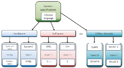
These modeling languages are generic and support different kinds of formalisms and concepts to enable a global and unified description of the system (architectural description, use cases, decomposition of the system, functional tasks mapping, configuration, and extra-functional properties). As a result, the structure of system specifications can be depicted as follows.
Figure 6 : Structure of system specification
Hence, the traceability of requirements aims at the wider question of information management and of documentation management within an industrial design process. We rely on this definition of the structure of specifications and consider that requirements and the resulting models at the different levels of abstraction are actually expressing different facets of the same system.
3.2.2 - ISDD: Integrated Specification, Design and Documentation
In [7], it has been proved how the exploitation of a centric representation of the information used as golden reference fulfils the needs in terms of consistency and traceability in the design flow of complex systems. It was shown how to address the duplicity of a common piece of information in multiple elements and guarantee consistency between its different occurrences, in a typical embedded system design flow. The approach offered focused on PCB and HW design and relied on the use of IP-XACT as common information backbone.
In the context of ACOSE, we developed a more generic and scalable approach in order to support the management of interdependencies between heterogeneous sources of information, addressing system design and documentation in a general manner.
3.2.3 - Most Reusable Units (MRU)
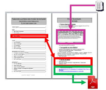
The actual principle of the approach is to consider any document or file (text, model, code, etc.) as a structured assembly of reusable information fragments which possess semantics on their own. The first step of the methodology consists in splitting files into assemblies of MRU of appropriate granularity that will be referenced. For example, a typical word document may be fragmented as shown below.
Figure 7: fragmentation of a MS Word document
Parts of the documents may be inputs originating from other derivate documents: component specification, business database, etc. or references to other sources. A piece of text in a specification may actually be an extract of another document (e.g. component specification, reference document, etc.). Some values can be extracted from business databases, probably in specific format, following construction rules and formalisms.
As these documents are usually evolving in parallel under the responsibility of different teams, the integration of evolution of content through all the documentation infrastructures is a tedious task, which fatally results in inconsistencies of information in different sources. By performing such fragmentation, we can consider the information agnostically of its containers and master its different occurrences in heterogeneous files in a similar manner, considering that each file is actually a subset of information related to the system following a specified structure.
3.2.4 - Assembly of MRU and publication
The aim of the approach is to go towards a merge of the different flows composing a development cycle (specification, design and documentation) by relying on a common backbone of information for the different activities. The considered fragments, i.e. Most Reusable Units, common to different representations of the system, are actually unique. The different files of the system are structured assembly of information, in which the occurrences of MRU are actually pointing to the golden reference of this MRU in files repository.
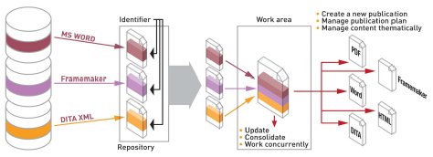
Figure 8: structured assembly of documentations
By dissociating information from the layout it is then possible to generate multiple publications in usual formalism (pdf, doc, html, xmlbased models, etc.) out of golden reference indexed contents, thus guarantying the consistency of information throughout the whole value chain.
3.2.5 - Example of resulting flow
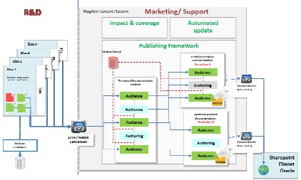
In this section, an example of instantiation of integrated flow is introduced, consisting in a unified design and documentation flow. MRU are referenced directly in the design files repository and made available to teams in charge of documentation and support within a publishing and editing framework. This framework allows the creation of documentation by including references to referenced MRUs.
Publications are enriched with contents that are specific to the documentation. Derivative documents can be created out of existing documents, preserving the references to MRUs contained in design files and in original documents. The layout is managed independently of the content; by relying on a specialized format i.e. XML DITA. The created publications are generated and then made available in usual documentation infrastructure.
Figure 9: Documentation infrastructure
The framework includes updates and evolutions monitoring functionalities, which detect precisely the nature and origin of changes in the indexed contents. By coupling the monitoring with impact and coverage analysis, users can efficiently manage the update and consolidation of information, ensuring consistency between design and associated documentation flow.
3.3 - Method for rigorous modelling of application and code generation
BIP (Behavior, Interaction, Priority) is a general framework encompassing rigorous design. It uses the BIP language and an associated toolset supporting the design flow. The BIP language is a notation, which allows building complex systems by coordinating the behaviour of a set of atomic components. Behavior is described as a Petri net extended with data and functions described in C. The transitions of the Petri are labelled with guards (conditions on the state of a component and its environment) as well as functions that describe computations on local data. The description of coordination between components is layered. The first layer describes the interactions between components. The second layer describes dynamic priorities between the interactions and is used to express scheduling policies. The combination of interactions and priorities characterizes the overall architecture of a component. It confers BIP strong expressiveness that cannot be matched by other languages. BIP has clean operational semantics that describe the behaviour of a composite component as the composition of the behaviors of its atomic components. This allows a direct relation between the underlying semantic model (transition systems) and its implementation.
The BIP design flow [1] uses a single language to ensure consistency between the different design steps. This is mainly achieved by applying source-to-source transformations between refined system models. These transformations are proven correct-by-construction that means, they preserve observational equivalence and consequently essential safety properties. Functional verification is applied only to high-level models for checking safety properties such as invariants and deadlock-freedom. To avoid inherent complexity limitations, the verification method applies compositionality techniques implemented in the D-Finder tool. The design flow involves 4 distinct steps:
- The translation of the application software into a BIP model. This allows its representation in a rigorous semantic framework. There exist translations of several programming models into BIP including synchronous, data-flow and event driven models.
- The generation of an abstract system model from the BIP model representing the application software, a model of the target execution platform as well as a mapping of the atomic components of the application software model into processing elements of the platform. The obtained model takes into account hardware architecture constraints and execution times of atomic actions. Architecture constraints include mutual exclusion induced from sharing physical resources such as buses, memories and processors as well as scheduling policies seeking optimal use of these resources.
- The generation of a concrete system model obtained from the abstract model by expressing high-level coordination mechanisms e.g., interactions and priorities by using primitives of the execution platform. This transformation usually involves the replacement of atomic multiparty interactions by protocols using asynchronous message passing (send/receive primitives) and arbiters ensuring overall coherency e.g. non-interference of protocols implementing different interactions.
- The generation of executable, monolithic C/C++ or MPI code from sets of interacting components executed by the same processor. This allows efficient implementation by avoiding overhead due to coordination between components.
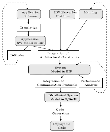
Figure 10: BIP design flow
The BIP design flow is entirely supported by the BIP language and its associated toolset, which includes translators from various programming models, verification tools, source-to-source trans- formers and C/C++-code generators for BIP models.
3.4 - Integrated low power design with IP-XACT
Energy awareness is a must for embedded software running on SoC, and this requires to access sensors and actuators values through registers all over the SoC. Those interactions ensure switching between its different functional modes. To formally describe those modes, an embedded hardware developer needs a tool to model the behavior of a component in accordance with its hardware specification.
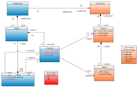
We developed a modeling behavior tool with state machines annotations. This tool enables hardware developer to model functional transitions of a hardware component with the use of sequence of access to registers. IP-XACT enables the use of a unified structure for the meta-specification of a design, components, interfaces, documentation, and interconnection of components [9]. For our case of study, we are focused of components specification. We have designed a state machine model of the behavior of a component which is then coupled to its IPXACT model. Furthermore, the hardware developer can annotate the state machine model with power values. Using execution trace analysis our tool is then able to build power reports, and state usage statistics.
Figure 11 : Link between models and power annotation
Our solution for power estimation using execution trace analysis is to replay trace against the state machine model to capture the duration of state activity and compute the crossing number of each transition. The power modes of each component are modeled with state concepts with a customized property annotation named “power”. A simple state machine diagram that illustrates one transition and two states is presented in Figure 12. This diagram is conforming to the component meta-model that is shown Figure 11.
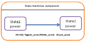
Figure 12 : Power State Machine
After modeling the behavior of a hardware component, the hardware developer adds measurement of power modes (in Watt).
In order to estimate power consumption, we have implemented an estimation framework that analyses execution traces and calculates the consumption of all component states.
We annotate state power consumption with ![]() (in joules) as it is shown in expression (1):
(in joules) as it is shown in expression (1):
![]()
And we annotate transition power consumption with ![]() (in joules) as it is expressed in expression (2):
(in joules) as it is expressed in expression (2):
![]()
Finally, we can get the value of power consumption for a specified scenario annotated with ![]() . It’s a sum of all state power consumption
. It’s a sum of all state power consumption ![]() and all transition power consumption
and all transition power consumption ![]() as it is showed in expression (3):
as it is showed in expression (3):

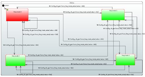
To validate the approach, we modeled a hardware component with our tool. As it is shown in figure 3, this component has four functional modes, named Freq mode 0 to Freq mode 3.
Figure 13 : Colored State machine in accordance with energy consumption
We then executed several scenarios on the component that conducted to several Freq mode usages. Using our trace replay tool we have then been able to produce the figures reported in Table 1 for both power usage and state duration.
The durations observed in the report are compliant to the real execution on the hardware, and therefore the timestamp information provided in the trace file is reliable.
The power profile and the overall energy budget are in the process of being checked against the hardware, using direct measure on the reference evaluation board.
| Power mode | Duration | Energy consumption |
| Freq mode 0 | 10.03 s | 5.02 J |
| Freq mode 1 | 1.02 s | 255.81 mJ |
| Freq mode 3 | 4.03 s | 251.90 mJ |
| Freq mode 2 | 2.01 s | 251.26 mJ |
Table 1: Results obtained after trace analysis
3.5- Fast simulation of multiprocessors systems
Simulation plays a central role both in the design of new architectures and in the development of application codes on these architectures.
Traditionally, embedded architectures where very ad-hoc and hardwired, but the rapid emergence of new standards in video, audio, radio, etc., and applications calls for more programmable devices, however still at a low energy level. One solution for flexible application specific circuits are multi and manycore architectures. However, most of these architectures are not readily available, and for those that are, cannot be made available to all programmers. Therefore, fast simulation is mandatory. In the Acose project, we leverage on the Rabbits [7] approach to simulate multi and manycore systems. Rabbits relies for the software side on a well-established dynamic binary translator called Qemu for cross-compiled software interpretation, and on the hardware side on the system level simulation industry standard SystemC. The Rabbits approach is a good trade-off in terms of simulation speed and accuracy while ensuring full cross-compiled software execution.
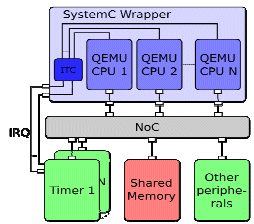
Figure 14: Overview of Qemu + SystemC integration
Several additions have been done to the original dynamic binary translator:
Ability to perform software timing and power estimates, by generating instrumentations instructions, which have not functional utility, within the executed code. Thanks’ to this innovation, metrics concerning software executions can be given, including abstract cache modeling, Optimized support for SIMD instructions [8]. Currently, the dynamic binary translators are using so called helpers to manage complex instructions in the target binary. However, all modern host processors also include SIMD extensions, so, and quite naturally, the idea of using the host SIMD instructions to handle the target SIMD instructions make sense. Unfortunately, there instruction sets are generally quite different, and therefore it is necessary to introduce an intermediate representation which can represent the parallel semantic of the instructions, and produce the appropriate front end and back-ends.
Support for Very Large Instruction Words (VLIW) architectures. VLIW processors have the particularity to execute several instructions at once, the parallelism being extracted at compilation time. So, all instructions which are being executed at the same time read their values from the same set of registers, and update their destination registers all together. Thus, as compared to the current dynamic binary translation approach which assumes a sequential execution, each register has to “live” more that the time for the host instruction that updates it. Indeed, it shall be updated only once all the inputs operands of all the parallel instructions have been fetched. To handle this case, it is necessary to have, for each physical register, a set of logical registers whose update process has to be monitored depending on the execution scenario. Other complications arise by the fact that some operations produce their results not 1 but several (but constant and known at compilation time) cycles after being issued, and that branches take effect also several cycles after having been evaluated. Overall, the VLIW support requires to deeply modify the binary translation process, and it is the first of its kind.
The mixing of SystemC event-driven simulation with Qemu dynamic binary translation gives the opportunity of doing fast hardware/software simulation, relying on an industry standard and a de facto mainstream processor emulator. Addition to both gives the ability to handle more efficiently more complex architectures, and also provides a way to do performance estimation at a high simulation speed.
4.EXPERIMENTS
4.1 - Automated generation of distributed code for sensor network
In this section, we illustrate the implementation of the BIP design flow described in Section 3.3 using the use case specified in Section 2. This case study is made of three distributed nodes which communicate in parallel. One master and two slaves. The master node synchronizes the slave’s clock sending periodically clock frame to slaves. In parallel, it plays audio samples captured and sent by slaves. When they receive a clock frame, slaves apply a PLL (Phase-Locked Loop) algorithm [6] to synchronize their clock.
The inputs of the BIP design flow are DOL/PPM specifications. They define applications and hardware specifications, but also the mapping of an application on a platform. A DOL/PPM specification is an XML format providing the possibility of referencing C files which can call libraries functions (Section 4.1.1). The BIP design flow uses DOL/PPM specifications either to automatically generate C code for a target platform (Section 4.1.3) or to generate a BIP model to analyze both functional and non-functional properties (Section 4.1.2). This design flow will lead to a framework for 1) the construction of faithful mixed hardware/software models and 2) the deployment of correct-byconstruction C code for applications in the domain of sensor networks.
4.1.1 Libraries Implementation
PPM model defines the specification of an application as KPN processes [2]. The behavior of each process is described by C files. In this particular use case, each process behavior is defined by calling synchronous component named SPM. Each component is identified by a structure, called SPM_filter, and associated with a set of functions. The SPM_filter structure, is defined as follows:
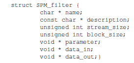
where the variable name is the component’s name, description depicts the component, parameter represents the component’s parameters, data_in and data_out are accordingly the component’s inputs and outputs, and stream_size, block_size their corresponding size. The functions associated with the structure SPM_filter are:
- init: initializes the parameters of the structure
- new: creates and initializes the structure SPM_filter
- preprocess: configures the component
- process: executes the component
- postprocess: finishes properly the execution of the component (for example, by closing file descriptors or sockets)
- uninit: deallocates the structure’s parameters memory
- destroy: deallocates the SPM_filter structure’s memory
- get: get the values of the structure’s parameters
- set: set the values of the structure’s parameters.
The instantiation of the component parameters and functions is application-specific. In [6], we describe with details the implementation of components required by the audio application of the Section 22, these components are:
- Micro: capture audio samples from microphone using the ALSA [3] audio library
- Player: playback audio samples by a speaker using the ALSA audio library
- Send: transmit data over wireless network
- Recv: receive data over wireless network
- Synchronize: periodically triggers timestamp for synchronization.
To test the above components, we instantiate the Micro and Send components in a main function. The role of the main function is to capture samples from a real microphone and sending them to a remote receiver which instantiates the components Recv and Player to respectively receive and playback the audio samples. In the beginning, we successfully tested the program using Ethernet. After switching to Wi-Fi, we observed that the program stopped with buffer overrun, meaning that the buffer configured by the component Micro in the ALSA library is full. To solve this problem, we changed the configuration of our Wi-Fi___33 network from mode g (low rate in theory) to mode n (high rate in theory). We also increased the size of the audio buffer in the audio library. This leads to a correct execution of the application until the network rate deteriorates. In the reception side, the application returns buffer underrun, meaning that the buffer configured by the component Player in the ALSA library is empty, due to:
- packet losses (in average 800 consecutive packets losses experimented)
- improper configuration by the component Player of the frame (sample from all audio channels) number available in the buffer before the first sample playback (playback threshold)
- improper definition by the component Player of the minimum frames available in the buffer before samples playback
- the deterioration of the network rate.
To compensate packet losses, we have defined in the component Recv the sliding window algorithm in which packets lost are replaced by packets where all bits are 0. To configure the playback threshold and the minimum frames available before playback, we analyzed the application with the use of BIP framework as described in the next Section.
4.1.2 Application Analysis
To analyze buffer underrun/overrun problem, we formally model the audio capture and its playback by a remote application in BIP. This model is analyzed using Statistical Model Checking (SMC). SMC [4] uses probabilistic distributions obtained through the real application executions. The constructed system model (Figure 15) consists of four atomic components. The Micro, responsible for the periodical sampling and generation of audio packets through the port SEND. The time needed for the generation of packets (PM) is fixed and thus considered a model parameter. The timing model is denoted by a discrete time step advance. It is associated with the port TICK and used to synchronize all the system components, which implement it (Figure 15). The processing of the data is done by the Network component, which is receiving the audio packets through the port RECV. The received packets are stored in a FIFO queue (TxBuffer).This component is modeling the behavior of the particular wireless network and therefore has a stochastic behavior. In the case of a successful transmission, each packet is assigned a value for its transmission delay derived from a delay probability law, whereas in the opposite case the packet is considered as lost. Whenever the transmission delay is expired, the packet is received through an interaction between the SEND port of the Network and the RECV port of the Buffer component (containing RxBuffer). The received packets will be played periodically by the Player component, through an interaction between its READ port and the REQ port of the Buffer component. The playback period is a model parameter referred to as PP. The behavior of each component is represented by finite-state automata, extended by data and functions, in order to handle audio packet transmissions in the model.

Figure 15: Audio Application System Model in BIP
The properties to analyze on the system model are the following:
- the TxBuffer size of the Network component should always be less than the estimated maximum size, in order to avoid a potential overrun
- the RxBuffer component should always have at least one packet in every request of the Player, in order to avoid buffer underrun
- the RxBuffer component size should always be less than the estimated maximum size, in order to avoid buffer overrun.
To evaluate the above requirements, we performed a number of extensive simulations using SMC and observed the probability to satisfy them. Some results are described below:
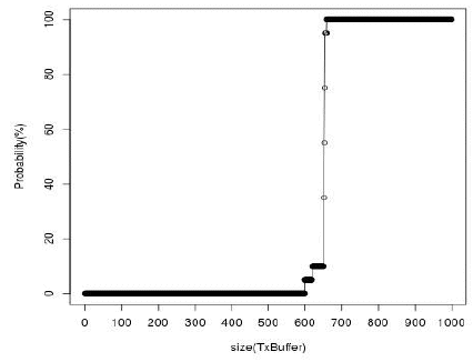
Figure 16: Probability of overrun in TxBuffer
As shown in Figure 16, the transmission buffer must be able to store more than 690 packets, in order to satisfy requirement 1. Additionally, the experiments for requirement 2 have shown strong dependence from the value of the initial audio playback period (p1). Specifically, (Figure 17) the requirement is satisfied only if its value is greater than 1430 ms.
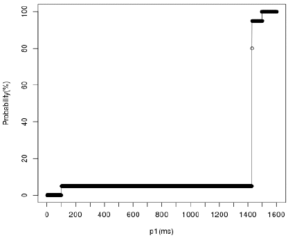
Figure 17: Probability of underrun in RxBuffer
More experiments are described in [6]. The values returned by these analyses are used to configure the application specification in order to generate a correct (w.r.t the properties analyzed) deployable code.
4.1.3 Automatic Code Generation
To generate the code, the BIP design flow uses a description language developed in Verimag named PPM (Pragmatic Programming language). This language extends DOL (Distributed Operation Layer) [5] for supporting hardware/software features (i.e. mutex shared memories). In PPM, application software is defined using an extended variant of Kahn process network model [2]. It consists of a set of deterministic, sequential processes communicating asynchronously through shared objects, such as FIFOs, shared memories and mutexed locations. The hardware architecture is described as interconnections of computational and communication devices such as processors, memories, buses and other communication media. The mapping associates application software components to devices of the hardware architecture, that is, processes to processors and shared objects to memories, which can be associated to remote communication media.
In PPM, specifications are described in XML. For example, Figure 18 presents a fragment of the audio application specification. For each process (speaker, micro), we specify the name of the process, the number of input and output ports, the names of the ports, the respective types and the location of the source C code describing the process behavior (implemented by the components Player and Micro). For each shared object (i.e. FIFO) we specify the name, the type the maximum capacity of data and the input and output port. Finally, we define the connections between the processes and the shared objects by specifying the input and output ports which contribute in each connection.
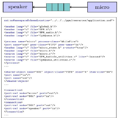
Figure 18: Audio Application XML specification
Figure 19 depicts the complete PPM specification of the application described in Section 2. The behaviour of the processes synchro and PLL are respectively implemented by the component Synchronize and by the Kalman Filter algorithm described in [6].
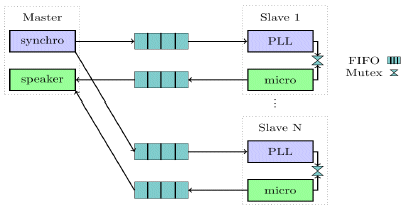
Figure 19: Complete Audio Application PPM specification
In the context of the ACOSE project, we target as platform a wireless sensor network (WSN) of spatially distributed autonomous sensors, which monitor sound (slave nodes) and cooperatively pass their data through the network to a main location (master node). For the current use case, we use a WSN that consists of three network nodes, as represented graphically by the Figure 20.
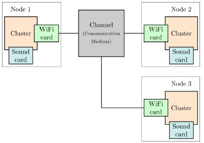
Figure 20: Sensor Network Abstract Model
The deployment of the use case applications on the target platform is specified with the use of a mapping XML description file. This description associates application processes to hardware node and provides the configuration to establish communications between the network nodes. An example of this XML file is given in [6]. Thus, the deployment (Figure 21) is making using threads for executing the processes and replaces the shared objects with communication primitives implemented using sockets parameterized with the User Datagram Protocol (UDP) protocol.
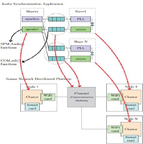
Figure 21: Mapping of the Full-Fledged Application on the distributed network
In Figure 22, we present the experimental results obtained on the Audio Synchronization case study. The Audio Synchronization application is deployed on a wireless distributed network consisting of three laptops connected over a WiFi local wireless network. Each laptop executes the part of the application deployed on it. In particular, the master runs the synchro and speaker processes, slave 1 executes the PLL1 and micro1 processes and slave 2 executes the PLL2 and micro2 processes. The results show the synchronization clock accuracy of the slave 1 and slave 2 clocks according to the master. We observe that until the 58 second the slave clocks are perfectly synchronized between them, but always have a small difference with the master clock. After the 60 second, one of the reasons of the difference between slave clock 1 and slave clock 2 is the scheduling time of processes PLL1 and PLL2 which is not the same for each slave because of the variant operating system load.
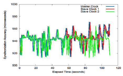
Figure 22: Synchronization Accuracy Using Kalman Filter
The illustrated results do not integrate network communication delays between synchro and PLL processes. However, in our ongoing work we plan to further analyze the accuracy of the synchronization algorithm taking in account the delays as described in [6].
5.CONCLUSION
This paper has presented various solutions grouped under the ACOSE’s framework and dedicated to the design of applications running on single or distributed hardware platforms. The general requirements of such designs have been listed and applied more specifically on a real industrial use case, experimental results have be conducted and proposed. We have seen that the supported levels of abstraction can cover models of the application alone, of the platform alone or system models that encompass the application on its platform both altogether. The design and verification flow which is the backbone of the methodology is based on industrial standards and is strengthened by the solution for fragmented documentation assembly and traceability management. Exploiting these models, a solution for integrated low power design with IP-XACT highlights the potential of the ACOSE framework to deploy innovative analysis technics. The academic proposals for rigorous modelling of application and code generation and for fast simulation of multiprocessors systems are boosting the needs for any industrial usage.
6.ACKNOLEDGMENT
This paper presents the technical results issued from the collaborative project named ACOSE. This project has been funded by France (Caisse des Dépôts et Consignation and DGCIS (Direction Générale de la Compétitivité, de l’Industrie et des Services) in the frame of a program called « Investissements d’Avenir Développement de l’Economie Numérique - Briques génériques du logiciel embarqué ».
The partners of the project are Magillem (project leader), CEA, Verimag, Tima and Cyberio.
7.REFERENCES
[1] A. Basu, S. Bensalem, M. Bozga, J. Combaz, M. Jaber, T.-H. Nguyen and J. Sifakis, "Rigorous Component-Based System Design Using the BIP Framework." IEEE Software, pp. 41-48, 2011.
[2] G. Kahn, "The semantics of simple language for parallel programming," in IFIP, 1974.
[3] "ALSA," [Online]. Available: http://www.alsaproject. org/main/index.php/Main_Page.
[4] B. Saddek, M. Bozga, B. Delahaye, C. Jégourel, A. Legay and A. Nouri, "Statistical Model Checking Qos properties of Systemw with SBIP," in ISOLA, Crete, Greece, 2012.
[5] L. Thiele, I. Bacivarov, W. Haid and K. Huang, "Mapping applications to tiled multiprocessor embedded systems," in ACSD, Washington, DC, USA, 2007.
[6] S. Djoko Djoko, D. Mauuary, A. Lekidis and P. Bourgos, "ACOSE Use Case: Distributed Audio Application," ACOSE, Grenoble, France, 2014.
[7] Marius Gligor, Nicolas Fournel, Frédéric Pétrot: Using binary translation in event driven simulation for fast and flexible MPSoC simulation. CODES+ISSS 2009: 71-80
[8] Luc Michel, Nicolas Fournel, Frédéric Pétrot: Speeding-up SIMD instructions dynamic binary translation in embedded processor simulation. DATE 2011: 277-280
[9] 1685-2009 - IEEE Standard for IP-XACT, Standard Structure for Packaging, Integrating, and Reusing IP within Tool Flows

