Gaurav Goyal, Reecha Jajodia, Shahab Akhtar; Freescale Semiconductor India Pvt. Ltd.
In a current trend of SoC Design, IC’s are becoming more and more complex so the challenges of meeting all the design requirements have become increasingly difficult. Expectations from current SoC’s are low power design and reduced die size with more & more features & hence logic. Though, it is impossible to meet all of these but what designers can ensure is that try to meet all of them to the extent such that there is no loss in other specifications.
Lot of power optimization strategy like power domains creation, usage of additional analog power switch-control circuitry which ultimately eats up some % of the saved power itself are employed by the design teams in order to reduce the power & also adds complexity to the design. Whenever there is an attempt to design a low power FF it would be done with a trade-off with the area or performance. Sequential elements & majorly Flip-Flops area can directly have an impact on the die size.
Conventional Flip-Flop architecture:
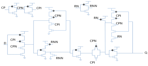
Fig. 1 depicts the conventional circuit for the Flip-Flop.
It has certain limitations:
a) When Reset ‘RN’ is asserted, i.e. RN = 0, It is highly probable that clock gets gated i.e. CP =0. But there is still some power dissipation due to toggling of “D” as input portion of master latch remains ON at CP =0.

Fig. 1: Conventional Flip-Flop design
b) To have the reset functionality, there is a need to have a signal ‘RNN’ which is invert of ‘RN’ which finally would eats up more transistors.
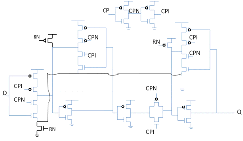
Proposed circuit has been implemented without the need of generating ‘RNN’ i.e. invert of ‘RN’ reset signal. This would solve the 2nd limitation with the conventional circuit.
Below is the proposed circuit (Fig. 2)

Fig. 2: Proposed Flip-Flop design
Doing this would provide area gain with additional below advantages:
- There is an increase in the no. of stacked structures in the non-timing critical path (feedback loops) which increases the threshold voltage of the device due to body-bias effect & saves power during reset assertion.
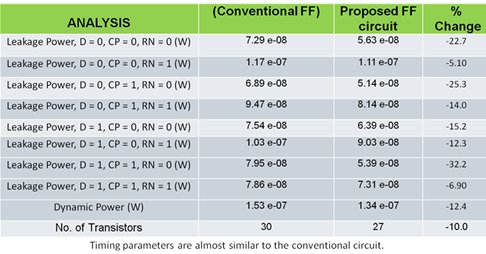
- No. of transistors used to implement the proposed circuit is 10% less than the conventional circuit; as can also be seen from the below Table 1.
Analysis of the proposed circuit:

Table1. Spice results between conventional & proposed circuit. (Leakage/Dynamic power comparison)
Table 1.shows that there is a huge reduction in the power dissipation across all the input conditions. Below is the analysis when CP & RN is ‘0’ & ‘D’ toggles:

Table2. Spice results between conventional & proposed circuit. (When clock & reset is ‘0’ & ‘D’ toggles)
Above analysis as in the Table 2 depicts that the 1st limitation of conventional circuit power dissipation when clock & reset is ‘0’ & ‘D’ toggles can be eliminated with the help of proposed circuit. There is a reduction of ~23% power.
Applications & Conclusion:
-
Spare Flip-Flops leakage gets reduced by more than 15 % as input RN is always tied to 1’b0.
-
There are always certain peripheral Flip-Flops whose “D” input continue to toggle even though their RN is asserted & clock is gated i.e. RN = 0 & CP = 0. Proposed art can save that power due to D’s toggling as well.
-
In general, proposed circuit is very instrumental for each & every conventional flip-flop replacement but gain is multifold with reset asserted.
It is clear from the above analysis, that there is a considerable savings in the leakage/dynamic power dissipation for the proposed circuit with considerable reduction in area also. All designs can use the proposed design architecture.
