Industry Articles
Safety Verification and Optimization of Automotive Ethernet Using Dedicated SoC FIT Rates-March 9, 2017 |
By Sachin Dhingra, Senior Product Marketing Manager, IP Group, Cadence; Apurva Kalia, Vice President R&D, Functional Safety Solutions, Cadence; and Robert Schweiger, Director, Automotive Solutions, Cadence
This article explains a new holistic methodology that combines analytic methodologies such as FMEDA with simulation-based methodologies to significantly reduce the safety verification effort and achieve faster product certification. Automated fault injection is a well-established test method used to verify the correct implementation of safety mechanisms and to get a much more realistic estimation of the FIT rates.
The automotive industry is working full steam on autonomous cars with two major goals in mind:
- To enable fully automated driving (a completely driverless car)
- To make cars safer by reducing traffic accidents
Advanced driver assistance systems (ADAS) leverage various sensors such as cameras, lidar, radar and ultrasound to fully sense the environment around the car. These sensors generate a very large amount of real-time data. High-speed communication-based Automotive Ethernet provides the bandwidth to further distribute the data within the car.
In addition to sensors, high-definition digital maps, high-precision positioning, cloud-based services, and vehicle-to-vehicle and vehicle-to-infrastructure (V2X) communication are needed to ensure the robustness, reliability and safety of self-driving cars. As a result, the electronic content of cars is increasing rapidly, relying on a new class of high-performance systems-on-chip (SoCs) to process all sensor data to control the vehicle in real time.
A dedicated functional safety verification process for these safety-critical SoCs is needed before they can be used in cars. ISO 26262 is an accepted standard used to ensure the functional safety in automotive systems. An extension of the ISO 26262 standard, Edition 2 (set to be published in 2018), will be dedicated specifically to address semiconductor-dependent failure analysis.
Improving Safety in Automotive Ethernet Applications
The automotive industry is trending toward Ethernet for in-vehicle networking (IVN) based on open IEEE standards. Driven by the OPEN Alliance SIG, these standards address the development of a simpler but more powerful automotive electrical/electronic architecture. Audio/Video Bridging (AVB) and Time-Sensitive Networking (TSN) are the key standards to enable Ethernet for automotive applications.
AVB enables time-synchronized streaming services through IEEE 802 networks. However, to meet the safety requirements of mission-critical control functions (such as camera-based driver-assist systems and emergency braking), a new set of open standards—collectively referred to TSN—is being developed. TSN enables robust, low-latency, deterministic and synchronized packet transmission in real time and is a super-set of the AVB standard. It supports safety-relevant mechanisms including:
- Frame pre-emption (IEEE 802.3br) to prioritize different data classes
- Frame replication and elimination to support a redundant path for reliable communication (IEEE 802.1CB)
- Send/receive packet verification/acknowledgement to indicate successful reception of data
- Policing and filtering functions (IEEE 802.1Qci) to detect and mitigate disruptive transmissions by other systems in a network (for example, to protect against “babbling idiot” faults), thus improving network robustness
- Redundancy in the master clock and failure detection, supporting real-time clocks (IEEE 802.1AS-Rev)
In the following example, we will focus on the high-speed communication within the car and analyze the impact of safety-relevant features of the Ethernet MAC (Media Access Controller) on the FIT rate and therefore on the overall ASIL (Automotive Safety Integrity Level) that can be achieved for Ethernet communication.

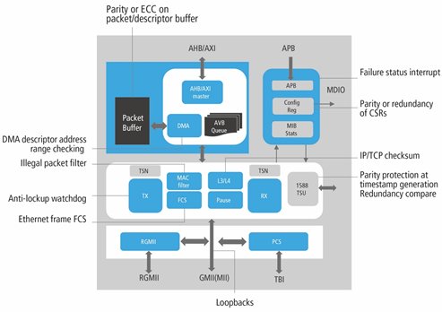
Figure 1: Safety mechanisms help to improve robustness of the Cadence Ethernet MAC
Combining Safety Analysis and Safety Verification
Since all safety-critical subsystems contribute to the overall safety of the car, a comprehensive safety architecture is key to achieve required safety goals. Safety features of the SoC are a critical part of the overall safety system. Hence it’s also important that safety features of the IP blocks can be leveraged at SoC level, reducing overall effort. The safety features of the IP should be designed while keeping this re-use in mind.
The main goal of a safety mechanism is to detect faults and to initiate appropriate measures, e.g., to get the system in a safe mode (Fail Safe) or even to correct faults to continue normal operation (Fail Operational).
There are various methods available to assess the overall safety level of a system. The primary goal of a Failure Mode Effect Analysis (FMEA) is to determine the effect of component failures on the system reliability or safety. In addition, the FMEDA Analysis determines the Safe Failure Fraction (SFF) and the Diagnostic Coverage (DC) of the system according to the requirements of IEC 61508 and ISO 26262 standards.
Input data for known failure modes for components and associated failure rates (Failure in Time (FIT)) is needed to analyze and, if necessary, optimize the overall safety level of the system. Since FMEA is a bottom-up approach, the accuracy of the analysis is heavily dependent on the accuracy of FIT rates at the lowest level. However, since this method relies on generally available FIT rates of standard devices, it does not work very well for application-specific SoCs because FIT rates are usually not available for design IP.
Therefore, FIT rate calculations tend to be estimations and are static in nature, by just looking at the structure of the design. Hence, these FIT rate estimations tend to be very pessimistic, which can lead to an over-engineering of the safety components of the design. A better approach takes into account only the actual failure modes, which look at the relevant safety mechanisms associated to each application.
Starting from a FMEA plan, the safety designer usually estimates the FIT rates for all components (IP) of the chip. A targeted fault injection allows them to simulate the influence on the system behavior and to classify faults. Fault classification using fault injection provides a more realistic estimation of the FIT rates as compared to the static methods, such as those based on catalogs.
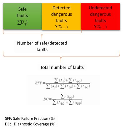
Faults can be classified in three categories:
- Faults that do not propagate into the system and have no negative impact on the correct operation of the system
- Detected faults that lead to a dangerous failure of the system
- Undetected faults that lead to a dangerous failure of the system
Fault classification at the observation points allows calculation of the Safe Failure Fraction (SFF) and the Diagnostic Coverage (DC) of the system. A SFF value of 92% is equal to a failure probability (PFD) of >=10E-4 to 10E-3. This corresponds to a Safety Integrity Level (SIL) of 3 and a failure rate per hour (PFH) of >=10E-8 to 10E-7. This results in a FIT rate of <100, corresponding at least to ASIL-C. As shown in the calculation (Figure 2), the safety level of the system can be considerably improved by better recognition of undetected dangerous faults.

Figure 2: Verification of a SoC safety architecture using fault injection
Ensuring Functional Safety in Ethernet IP
Multiple safety mechanisms have been added to the Cadence Ethernet MAC IP to make it functionally safe for automotive SoCs, such as in ADAS applications (Figure 1). In addition, a well-defined methodology, tool support based on a highly integrated verification flow, is needed to enable an automated safety verification of all safety mechanisms for complex SoCs.
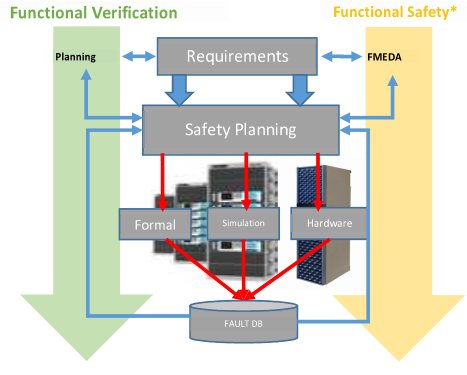
Safety verification and functional verification need to go hand in hand. Simulation results generated during functional verification can be re-used for safety verification, as well:
- Standard techniques like FMEDA and Fault Tree Analysis (FTA) are used to create a structured safety plan documenting all the safety mechanisms for the design—either as safety element in context or out of context.
- Failure modes should be connected to the design elements to calculate accurate FIT rate distributions. For safety elements that have a dynamic behavior, FIT rates based on catalogs are not accurate enough. Connecting the failure modes to the design makes it more accurate.
- A fault injection campaign should be linked to the FMEDA report. This makes the fault campaign more realistic as opposed to doing a blind fault campaign.
- A central fault database is essential—since the solution will use multiple engines, all engines must be able to talk to each other and share data, which implies a scalable, searchable central database.
Fault injection is a very compute-intensive process. There are many different types of execution engines available for fault injection:
- Software-based simulation engines (such as the Cadence Incisive Functional Safety Simulator)
- Hardware-assisted engine (Cadence Palladium platforms)
- Formal methodologies (Cadence JasperGold platform)
We need to use all available engines to get the best throughput for fault injection. A simulation-based engine can be used for short tests, for complete regressions, and in scenarios where detailed debug is required. A hardware-assisted engine can be used for long latency tests and software-based tests for the complete SoC. A formal engine can be used to formally reduce the fault injection space by doing formal logical and equivalence analysis.
A smart combination of all the above techniques is important for effective functional safety verification. Therefore, for the Ethernet MAC, the functional verification was first done with the safety features switched off, which provided the baseline metrics for the function. The safety features were then switched on to assess the behavior of the design under functional safe modes. This also enabled us to measure the metrics like Single Point Failure Rates and Diagnostic Coverage, and ensure that they meet our qualification requirements.
The most efficient way to measure the above-mentioned metrics is using fault injection at defined fault injection points—both for permanent faults as well as for transient faults (Figure 3). FMEDA results can be used to identify an optimal set of faults to be injected. Fault strobe points are identified before and after the safety mechanisms that can be connected back to the Failure Modes in FMEDA. The faults are detected by comparing the results of the simulation with and without fault injection. Any mismatch in values—including the time at which these values occur—causes the fault to be detected. Only injected faults that propagate through the system to the observation point can be recognized by the subsequent safety mechanism and can be fixed by an Error Correction Code (ECC).

Figure 3: Combining safety analysis and safety verification
The functional safety solution and methodology described above is a structured and scalable methodology, which means that the FMEDA created and the metrics measured can be fed into a larger SoC that is using this IP. This process allows the user to re-use the work that has been done at the IP level at the SoC level and to achieve a higher quality at the SoC level.
In the case of Ethernet MAC IP, our goal was ASIL-B. This goal was achieved with the addition of proper safety mechanisms, as shown in Figure 1. Future versions of the IP will target higher levels of ASIL certification.
Summary
For a safe Ethernet-based communication complex, automotive SoCs need appropriate IP including safety mechanisms and protocol support. In addition, a scalable methodology is necessary for safety verification. A holistic methodology that combines analytic methodologies with simulation-based methodologies helps to significantly reduce the safety verification effort and achieve faster product certification according to ISO 26262.
Automated fault injection is an appropriate test methodology for verification of the implementation of safety mechanisms and provides an accurate estimation of the FIT rates for a FMEDA analysis. This makes clear why support of protocol standards such as TSN as well as comprehensive safety mechanisms for fault recognition are important for automotive designs. The Cadence Automotive Ethernet MAC supports all common protocol standards and ensures a secure and deterministic real-time communication.
About Authors
 | Sachin Dhingra is a Senior Product Marketing Manager in the IP Group at Cadence Design Systems Inc. responsible for PCIe, Ethernet, and MIPI Interface controllers. Prior to Cadence, he held positions in marketing, sales and engineering groups at Altera (now Intel) and Achronix. Sachin received his MS in Electrical and Computer Engineering from Auburn University. |
 | Apurva Kalia is Vice President of R&D at Cadence Design Systems Inc. responsible for developing the Functional Safety Solution. He has 28 years of EDA tool development experience, and has previously managed the Cadence logic simulation and formal based verification technologies. Apurva has a Master’s degree in Computer Architectures. |
 | Robert Schweiger is Director Automotive Solutions, EMEA at Cadence Design Systems Inc. responsible for the Automotive business development. In this role he is driving the development of Automotive Solutions across all Cadence product lines covering tools, IP and services. He is also representing Cadence as a technical member at the OPEN Alliance SIG to help to define the requirements for the deployment of Automotive Ethernet in cars. Robert has a master degree in Electrical Engineering. |
