By Muhammad Aslam, Anıl Çelebi, Kocaeli University
Izmit/Kocaeli Turkey
Abstract:
Increasing functionalities of application specific integrated circuits (ASIC) require rather more efficient verification methods. In this paper, a novel verification model (VM) for low complexity motion estimation (ME) hardware architecture used in a video encoder is proposed. MATLAB, C and SystemVerilog based hybrid VM is proposed. A multilayer based approach is adopted where a generator, agent, driver, scoreboard, monitor and checker is utilized. Object oriented programming (OOP) capability of the SystemVerilog makes the VM more efficient and reusable compared to the existing VMs presented in the literature. Additionally, functional coverage of ME algorithm is also performed. According to the experimental results it can be concluded that such a verification approach is a proper solution for verifying complex signal processing integrated circuit (IC) designs.
Keywords: SystemVerilog, verification, motion estimation, Functional coverage, object oriented programming.
1. Introduction:
With the passage of time, the number of different functionalities integrated on a single ASIC chip is increasing dramatically; therefore, ASICs are becoming more and more complex. Verification of such ASICs has become a major challenge in this era of technology. The more ASICs become complex, the more verification time is needed. It is roughly estimated that 70% of total time through the design of a chip is spent for verification [1]. Verilog and VHDL, collectively called as hardware description language (HDL), can be used for describing integrated circuits (IC) but they are not efficient enough for verification process. Different languages have been used for functional verification (FV) of ICs. SystemVerilog is being used for more than 10 years in the industry for verification purpose. SystemVerilog is the improved form of Verilog with lots of new features such as OOP. SystemVerilog with OOP is exploited to make VM more reusable for device under test (DUT) [2, 3, 4]. SystemVerilog can be used for design as well as verification. In [5], verification intellectual property (IP) is designed by using SystemVerilog. Recently, many new features have been included in SystemVerilog such as assertions, functional coverage, randomization and communication interface between different threads which make SystemVerilog as the most promising language for verification of recent complex ICs.
In [6], functional coverage features of SystemVerilog are highly utilized in the design of VM for the DUT. In [7], coverage driven constraint random stimuli generation based VM is presented for a DUT. Integration of different programing languages in a VM makes it more reusable and efficient if the interfaces between different programming languages are well defined. In [2], SystemC is utilized in addition to SystemVerilog which increases the reusability of VM. Reusability of VM can be increased further by adding more programs into the verification environment. There are several other languages that are used for verification purpose e.g SystemC, Specman e etc [2, 11]. SystemC along with SystemVerilog is exploited to realize a hierarchical VM in [2].
In this paper a novel multilayered VM is presented for the low complexity motion estimation (ME) hardware architecture presented in [10]. SystemVerilog is integrated with C and MATLAB in this hierarchical VM for the first time in the literature. This kind of multilayered VM makes verification process more reusable and efficient especially for signal processing hardware architecture design where MATLAB/C is first used for algorithm development and then Verilog/VHDL/SystemVerilog is used for architectural implementation and directed tests [10].
2. DUT description
In this paper ME hardware architecture introduced in [10] is used as DUT. Architecture of DUT is shown in Fig. 1. Shift registers are used to store current block (CB) and search window pixel data. The width of the shift registers is three bits. At the output of shift registers, 3×1 multiplexer array is used to select appropriate bit from the three incoming bits in accordance with the algorithm described in [10]. After that, exclusive XOR operation is performed and number of non-matching pixels (NNMP) is calculated. The candidate location having the minimum NNMP value represents the motion vector (MV) of the respective CB.
3. Proposed Verification Model
Proposed VM for the DUT is shown in Fig. 2. A multilayered scheme is used in the VM as explained in [8]. Proposed VM mainly have six subcomponents; generator, agent, scoreboard, driver, monitor, checker and interface. In the VM, stimulus and expected outputs are generated according to the test plan shown in Fig. 5. After that, stimulus is applied to DUT and expected outputs and DUT’s outputs are compared to verify the functionality of the DUT.
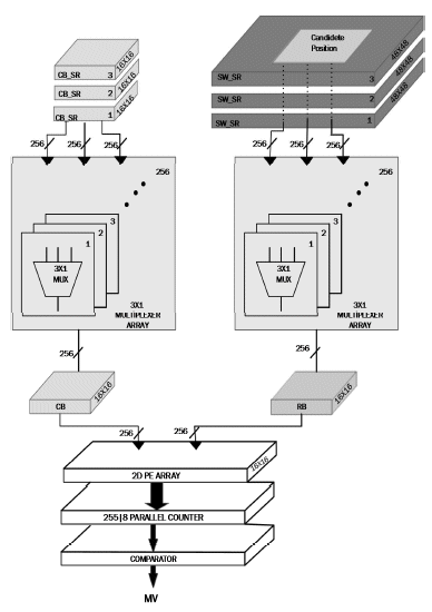
Fig. 1 Architecture of the DUT[10]
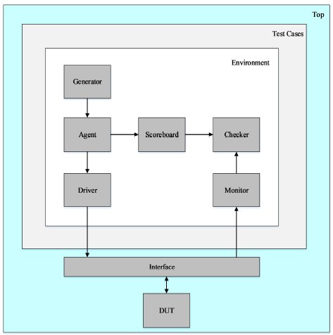
Fig. 2 Verification Model
3.1. Generator
Generator is mainly used to produce test stimulus according to test plan. In the proposed VM, the generator’s duty is to pick video sequence, a frame in the sequence and current block location in the frame randomly. Since number of video sequences, video frames, and block locations are in a definite range this random selection must be constrained within a certain range. This is implemented by using constrained randomization functionality provided within SystemVerilog. An example randomization script is shown as,
rand [1:0] bit video;
constraint vid_c {video≥0;video≤2;} (1)
Where rand [1:0] bit video generates random data uniformly between 0 and 3 and constraint vid_c {vid≥0;vid≤2;} restrains the generated values of video between 0 and 2. Video frame and block locations are randomly selected within [1,40] and, [2,15] respectively by using same approach. The information generated for video sequence, video frame and block location selection data are saved in a text file.
3.2. Agent
In the proposed VM, agent is mainly used to drive the scoreboard and the driver. Within agent, C function is called by using direct programming interface (DPI). Within C code, Microsoft Visual Studio (MVS) is invoked by calling its .exe file. MATLAB is invoked by using engine library provided by MVS. MATLAB then invokes the respective .m files in which the transaction level description of the ME algorithm is found. Two text files are generated by the related .m files. One text file contains expected NNMP values and expected MVs while the other file contains CB and reference block (RB) pixel data applied to the DUT as shown in Fig. 3.
3.3. Scoreboard
Generally, a scoreboard is used to produce the expected values that are used to compare with the outputs generated by the DUT to verify the functionality of the DUT. In the proposed VM, the scoreboard contains the expected NNMP values and MVs generated by MATLAB.
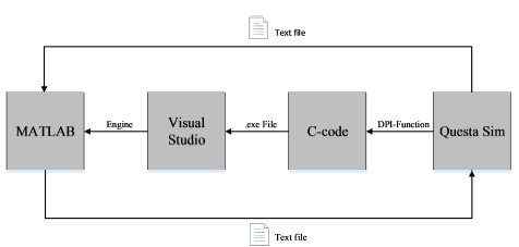
Fig. 3 Integrated Verification Approach
3.4. Driver
The driver is used to drive the DUT with the test stimuli generated by the object oriented test environment. Driver stimulates the DUT by applying CB and RB pixels received from the Agent. Reset and clock signals of the DUT are also generated by driver. Driver is responsible for maintaining the synchronization between the DUT and the test-bench.
3.5. Monitor
The function of the monitor is to collect the outputs of the DUT and transmit them to the Checker block in Fig. 2 that is an object oriented component. In this paper, the outputs of the DUT are NNMP values and MVs.
3.6. Checker
In this block, expected outputs and outputs generated by DUT are compared to verify the functionality of the DUT. In the proposed VM, expected NNMP values and MVs generated by scoreboard are compared with NNMP values and MVs produced by DUT. This information is used to assure that either DUT is working correctively or not.
3.6. Interface
Generator, agent, scoreboard, driver and checker blocks are implemented by using OOP approach thus, they are dynamic objects. On the other hand, DUT is implemented by using synthesizable subset of the Verilog language and in Verilog the fundamental building blocks are modules that are static. Interfaces are used to isolate the static and dynamic part of the proposed VM. Since proposed VM is a hierarchical model, virtual interfaces are exploited to establish a proper communication channel between submodules. An example script of an interface is shown in (2),
Interface bus (input bit clk);
bit clk_en;
endinterface (2)
Where, clk represents the global clock of the VM and, clk_en signal is used to enable clk. For simplicity, other signals used within interface are not shown in (2). Furthermore, interfaces avoid the driver and monitor connecting to the DUT directly which further improves the reusability of verification model (VM) [9].
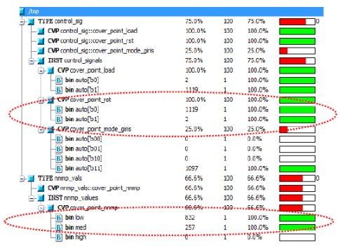
Fig. 4 Functional Coverage
4. Functional Coverage
The progress of a test plan being executed should be observed by using functional coverage to enable a dynamic verification process. It is basically a code fragment written to track whether important values or set of important values that relate to the critical points of the design are investigated. In DUT, 16×16 size CB is used to generate 1089 different NNMP values where the location having smallest NNMP value represents the MV of the respective block. In the proposed VM, functional coverage is implemented in two different cover groups to observe the control signals and data signals respectively. Control signals cover group has reset, load and mode_giris signals and data signals cover group has 1089 NNMP values. An example of 16×16 block is shown in Fig. 4. In control cover group, it can be seen that mode_giris is covered 25 percent while all other control signals are covered 100 percent. Since mode_giris is signal of size two bits, it can have four different values. Algorithm described in [10] states that only one of four possible values can be assigned during ME process. Therefore, mode_giris represents 25 percent coverage in the report which means full coverage is achieved. In NNMP cover group, all 1089 values are exercised.
5. Test Plan
In the proposed test plan, following features are verified.
- Reset signal should make the system to idle state.
- All 1089 NNMP values for each 16×16 CB should be exercised
- For power estimation of the low complexity ME hardware architecture, the whole 16×16 region shown in Fig.4 should be covered.
- The verification environment and the DUT should be synchronized.
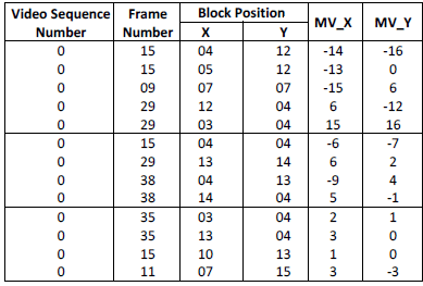
Feature 1 and 2 of test plan are implemented with two cover groups in the functional coverage and their results are shown in fig.4. 3rd feature is realized in generator module of verification environment. Constrained randomization is exploited in the generator module to select video sequence, a frame in the sequence and current block location in the frame randomly. Thanks to this kind of randomization which helps to cover all the sub-regions shown in Fig. 5. ME algorithm generates MVs. According to generated MVs, 16×16 region is divided into 3 sub-regions. Ranges of these regions are shown in Fig. 5. Experimental results of these three sub-regions are shown in Table 1. All three regions are covered in the Table 1. Power estimation of the low complexity ME hardware architecture can be estimated by using data shown in Table 1. 4th feature of the test plan is implemented in driver module of verification environment. In driver module clock enable signal is used to enable and disable the global clock of the DUT.
6. Conclusion
In this paper, novel verification model for low complexity ME hardware architecture presented in [10] is proposed. In the proposed VM; MATLAB, Microsoft Visual Studio and Questa Sim environments are integrated for the first time in the literature. This kind of integration increases the reusability of VM by isolating algorithm development and design/verification spaces. Furthermore, functional coverage is used to check the functionality of the algorithm proposed in [10].

Fig. 5 Test Plan
Table 1. Random Test Rresults
Acknowledgment:
This work is supported by TUBÄ°TAK under project number 115E921.
References:
- Wenfeng Zhong, SystemVerilog and functional verification, 1st ed. China Machine Press, 2010, pp.1, 154-155.
- Zhou, Zhili, Zheng Xie, Xin'an Wang, and Teng Wang. “ Development of verification envioronment for SPI master interface using SystemVerilog.” In Signal Processing (ICSP), 2012 IEEE 11th International Conference on, vol. 3, pp. 2188-2192. IEEE, 2012.
- Oh, Young-Jin, and Gi-Yong Song. “Simple hardware verification platform using SystemVerilog.” TENCON 2011-2011 IEEE Region 10 Conference. IEEE, 2011.
Myoung-Keun You, Gi-Yong Song. “SystemVerilog-based Verification Environment Using SystemC Custom Hierarchical Channel”, IEEE 8th conference on ASIC, pp.1-4, 2009.- Han Ke, Deng Zhongliang, Shu Qiong. “Verification of AMBA Bus Model Using SystemVerilog. 8th International Conference on Electronic Measurement and Instruments”, pp.776-780. 2007.
- Ma, Pei-Jun, Yong Jiang, Kang Li, and Jiang-Yi Shi. “Functional verification of network processor.” In Electronics, Communications and Control (ICECC), 2011 International Conference on, pp. 1472-1475. IEEE, 2011.
- Wu, Yingpan, Lixin Yu, Wei Zhuang, and Jianyong Wang. “A coverage-driven constraint random-based functional verification method of pipeline unit.” In Computer and Information Science, 2009. ICIS 2009. Eighth IEEE/ACIS International Conference on, pp. 1049-1054. IEEE, 2009.
- Bergeron, Janick, Eduard Cerny, Alan Hunter, and Andy Nightingale. Verification methodology manual for SystemVerilog. Springer Science & Business Media, 2006.
- Spear, Chris. SystemVerilog for verification: a guide to learning the testbench language features. Springer Science & Business Media, 2008.
- S. Yavuz, A. Çelebi, M. Aslam, O. Urhan, “Selective Gray-Coded Bit-Plane Based Low-Complexity Motion Estimation and its Hardware Architecture,” IEEE Transactions on Consumer Electronics, Vol. 62, No. 1, pp. 76-84, Feb. 2016.
- Kuhn, Tommy, Tobias Oppold, Carsten Schulz-Key, Markus Winterholer, Wolfgang Rosenstiel, Mark Edwards, and Yaron Kashai. "Object oriented hardware synthesis and verification." In System Synthesis, 2001. Proceedings. The 14th International Symposium on, pp. 189-194. IEEE, 2001.
About Authors:
 Muhammad Aslam was born in Bahawalpur, Pakistan. He received the B.Sc., degree in electronics engineering from International Islamic University, Islamabad, Pakistan, in 2014. Since 2015 he has been with the Department of Electronics and Telecommunications Engineering, University of Kocaeli, Turkey, where he is student of master degree. His current research interests include video coding/motion estimation: algorithm and implementation using FPGA.

Anıl Çelebi (S’00, M’09) was born in Ordu, Turkey. He received the B.Sc., M.Sc. and Ph.D. degrees in electronics and communication engineering from Kocaeli University, Kocaeli, Turkey, in 2002, 2005, and 2008, respectively. Since 2002 he has been with the Department of Electronics and Telecommunications Engineering, University of Kocaeli, Turkey, where he is currently working as an Assistant Professor. He worked as a BK21 Post-Doctoral Research fellow at the School of Electrical Engineering and Computer Science at Seoul National University, Korea between April - July 2009. His research interests include very large scale integration (VLSI) design and implementation for analog/mixed signal systems, image processing and video coding systems.
