By Santanu Bhattacharyya, Rohit Chaturvedi, Bhupendra singh, Nitin Goel (Solarflare Communications)
1 Introduction
Semiconductor industry is growing with tremendous pace. Silicon size, features and software complexity have increased to a never before level. Time to market has been reduced and the demand for quality of product has increased. Once the product definition is available the development cycle starts. Development cycle has many phases like architecture, design, verification, software development and testing, emulation and silicon validation.
To meet the time-to-market target, there is always a need to bring parallelism to the product development cycle. Though design and verification are done in parallel, the software development generally starts a bit late and continues till product delivered to the end customer. As software is not tested fully before the silicon fabrication, this leads to re-spin of silicon sometimes and also leads to delay of the product delivery.
With the advent of constraint based random simulation, verification has become more robust from its earlier versions. While these random test-benches are helpful to cover corner cases at lower layers of abstraction, it is not enough to find system level behaviour of the design when it is integrated with software. For this it is necessary to run simulation of hardware logic along with software. This is where hardware/software co-verification using SystemVerilog Direct Programming Interface (DPI) comes into picture. Mostly DPI used to provide access of C/C++ libraries to SystemVerilog. Co-Verification setups use DPI for interfacing hardware with software. In most cases, SystemVerilog/UVM is used to generate stimulus which is then transferred to either a (SystemC based) virtual platform or an emulation platform. In this scenario, the DPI is used to drive software transaction to the DUT. QEMU(Quick Emulator) based virtual platform has been integrated with SystemVerilog based RTL simulation environment. Transactions are generated by actual software (Application) running on QEMU. The SV environment captures these transactions through DPI and drives them on the DUT interfaces. This paper proposes a flow which illustrates how to develop and test software early in the development phase along with design-verification cycle. Also this paper highlights the benefits of the flow which will not only reduce the development cycle but also improve the quality of product.
2 Overview of DUT (Design under Test)
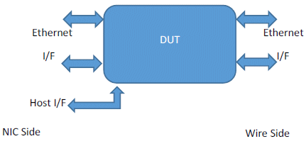
Traditionally, network traffic is processed on processor where there is a NIC (Network Interface Card) interfacing the network i.e. wire side through Ethernet interface and software taking care of the packet processing. There are numerous applications where Processor based packet processing might be inadequate to meet the processing latency requirement. Applications such as High frequency trading and online advertisement demand extremely low processing latencies. To meet this type of latency requirement it is better to process the packet on a dedicated hardware along with the NIC and communicate to the software processor farm. The dedicated hardware i.e. the DUT is shown in Figure 1 below as co-processor to NIC having Ethernet interface on both the NIC and the wire side. The NIC interfaces with the host over PCIe bus and on the network side it has Ethernet interface. The DUT in addition to the Ethernet interface also has host interface for configuration and device status monitoring purpose.

Figure 1: DUT Block Diagram
3 System Verification Environment
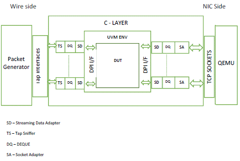
In the Verification Environment shown in figure 2 below has Packet generator which can be a system Verilog packet generator or user world application called PackETH. PackETH provides GUI interface to customise the packets by controlling addresses, payloads, length of packet, packet type etc. Apart from these it can also provide corrupted packet to check error scenarios.
Tap interfaces (virtual interfaces created by Linux command tunctl) are special software entities which instruct the Linux machine to forward Ethernet frames. In other words, the virtual machines connected to tap interfaces will be able to transmit and receive raw Ethernet frames. And due to this virtual machines can continue to emulate physical machines from a networking perspective.
C-Layer has tap sniffers which acts as interface between DEQUE & tap interface. DEQUE is a temporary storage queue in which it takes data from both direction transmit as well as receive. C-Layer communicates to QEMU through TCP sockets.
Streaming Data Adapter (SD) converts Ethernet frames to be compatible with DUT proprietary interface and passes it to DPI interface.
UVM Environment instantiates the DUT, Monitors, Scoreboards, Models and Drivers. In early stage of design cycle when the DUT is not available, a DUT model in place of actual DUT (in C++/UVM) can be integrated to start the early development of Software. The DUT model can be developed in C++ or UVM.
QEMU is a hosted virtual machine. It emulates CPU and provides a set of device models, enabling it to run a variety of unmodified guest operating systems. QEMU has Hardware Abstraction Layer (HAL) layer and it runs the Host side application. HAL is a hardware abstraction layer which is provides API to configure design (DUT).
Socket Adapter is used for inter-process communication and it uses the client server model. Here QEMU is Client and C-Layer is server. The client connects to the server for exchange of information. QEMU interacts with C-Layer using socket adapters for configuring the DUT, transmit packet to the DUT and receive packet from the DUT.
Control and Data Flow:
Control path transaction is generated by the application software running on QEMU and these transactions through the DPI calls will be captured by the UVM environment and there it will be driven on DUT on various interfaces.
PackETH generates Ethernet traffic which is pumped into the tap interfaces. This tap interfaces captures the packet in D-queue inside C-layer and then the packet is passed onto the UVM Environment through DPI calls. At NIC side processed packet (output packet from DUT) is passed to C-layer which connects to QEMU through sockets.

Figure 2: System Verification environment with DUT
3.1 Software development Environment

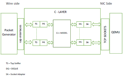
Figure 3: Software development environment with C++ model
At the start of project when actual hardware is still under development a software model of the DUT is developed and integrated. The software model is either untimed (written in C/C++) or (when performance benchmarking is required) a loosely timed model written in SystemC. Most hardware designs constitute multiple interfaces to the external world so C++ model has to support multiple ports.
3.2 Software Model Architecture
Linux allows two types of shared-memory threading: Pre-emptive threading (posix threads) and Cooperative threading. In Cooperative threading single thread is executed at a time so a single processor is utilized. Pre-emptive threading multiple threads can run at one time so Operating system is required to control the operation. Posix threads are mostly used in embedded software – especially software working with multiple interfaces. . Since there are multiple interfaces which are active simultaneously, a separate posix thread is dedicated to each interface. Since multiple threads run simultaneously and use shared memory, software races are possible. Special care is required to avoid race conditions.
Concurrency issues faced with multithread applications are: Thread Races and Thread Starvation. Thread race occurs if two threads simultaneously try to access shared data. “Mutex” module is used from C++ boost library to avoid race conditions. To make threads efficient, a separate Mutex lock is created for each shared data queue.
3.3 SV Simulator interfacing issue with Software Multithread
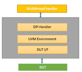
When Actual design comes DUT (with UVM Environment) is integrated in the environment as shown in figure 2. Since these are two different system which has inherent challenges to integrate. System Verilog(SV) Simulators predominantly execute on single thread. So the question arises as to how to integrate SV Simulator, single threaded system, with software multi-threaded system. Solution is to design a software module which takes care of multiple threads and socket handling. It is named as “Multithread Handler” as shown in figure 4. This multithreaded handler is present in socket adapter block. Simulator through DPI calls, attaches with the main thread of the multi-thread handler, which in turn spawns all other independent threads required for handling socket and virtual interface data. Main thread waits for notification and then locks each queue one by one looking for transaction. Mutex locking has been used for it. Mutex, helps protect shared data and avoid thread races. To make threads efficient, a separate Mutex lock is created for each shared data queue. Since all the forks are executed on the same processor in a determined order, there is no scope of software race conditions.

Figure 4: Transaction Flow
4. Benefits of Flow
4.1 Development Cycle
- Development cycle reduction: Development time will be reduced as software development and system test can be addressed early in development phase.
- DUT model: Since it is plug-n-play environment, DUT can be replaced by the DUT model. Earlier verification and software team used to develop different model, but now only one model can be developed which can be used by both the team. Same model can be used for Software unit test, hardware block level test and for system test.
- Single Environment for Unit to system level test: The environment will be seamlessly used for Software Unit testing and System level testing.
- Legacy software compatibility check: Most of the time customers who are using enhance product wants the legacy software to be back-compatible. This flow will enable to test customer legacy software and any issue can be fixed upfront.
- Post Silicon support: Issues reported by customer while running on field can easily be replicated and checked without changing customer software. Same software which customer is running can be easily ported and verified on this platform.
4.2 Quality
- Customer use cases: System level scenarios supporting customer use cases can be run to improve the quality of design.
- . Robust Generator: Many a times design breaks when tested against actual data generators. This flow will help to plug traffic generator utility like PackETH which generates bus traffic very close to the traffic generator used in the field.
5. Conclusion
SW driven mechanism provides a convenient way to drive transactions at DUT through higher levels of abstraction. By enabling the hardware test along with Software, it not only improves the product life cycle but also the quality of deliverables. It helps to avoid finding design or architecture issues at late stage. It also provides the platform to test the legacy software and find issues upfront.
6 ACRONYMS
- QEMU Quick Emulator
- UVM Universal Verification Methodology
- SV System Verilog
- DUT Design under Test
- GUI Graphic User Interface
- NIC Network Interface Card
- API Application Programming Interface
7REFERENCES
- A. F. et al, “Hardware/software co-verification using the SystemVerilog dpi.” DVCon, 2013
- S. Sutherland, “Integrating SystemC models with Verilog using the SystemVerilog direct programming interface.” SNUG, 2004
