By Andrea Leopardi, Niclas Jansson, Pieter van der Star, BitSim AB
Introduction
For almost 20 years, BitSim has developed embedded systems. During these years, we have seen customers who are uncertain of the system requirements and some of them were, and are, unsure of their functional requirements. This does not match well with traditional FPGA development, where a development cycle takes days, if not weeks. Where a customer wants a “simple” functional change, for an FPGA developer, this is not always that simple. With the internet of things (IoT) becoming a reality, companies that before did not need a smart system are now searching for solutions to integrate their existing designs into an IoT device easily. At BitSim, we have a way to simplify and speed up the development cycle. In this document, we will discuss the issue of network load in an IoT environment as well as "our" way to speed up the development.

Central or distributed processing
The recent trend has been to run everything in the cloud. There, a centralized solution, such as a server, is handling the massive amount of data from the IoT devices. This solution may not be the best for all kinds of applications. What if the network bandwidth is limited or it is very costly to send data over the cables or wireless? What if you’re concerned about the latency? If sending data over the network takes a relatively long time, this inhibits a quick response for decision making. Maybe it is better to compress or filter all the data before sending it over the network. Sending just enough meaningful data to the cloud, thereby improving performance, cost and/or security.
If your application needs near real-time processing or low-latency performances, the concept of a distributed platform or Edge Computing1 may be a better choice. It may also offer lower operational costs and reduce traffic on the network.
Advantages of Edge Computing
In Edge Computing, some or all processing is performed close to the data sources. In this way, latency is reduced, and thus analysis can be carried in real-time or near real-time. An example demanding these characteristics can be found in the field of Advanced Driver-Assistance Systems (ADAS) and Autonomous Vehicles, where the vehicle must be able to analyse data locally.
If the processing were entrusted to a remote unit, the vehicle would have to transmit a large amount of raw data first, then wait for that data to get processed and results sent back, with critical effects on time for action in a traffic environment, not to mention a vulnerability to network attacks. Therefore, centralized platforms must also rely on a more robust communication network than Edge Computing solutions, with an associated higher cost for scalability.
FPGA SoC Evolution
Edge computation is easier than ever and can be handled by CPUs, GPUs, FPGAs or ASICs.
All the major FPGA vendors have their own version of FPGA SoCs (System on Chip), which contain both a CPU and FPGA in tandem. Xilinx has Zynq 7000 and MPSoC, Intel is just calling them SoCs, and Microchip/MicroSemi has SmartFusion SoCs. These are featuring more and more efficient capabilities making them an attractive solution for many applications. A typical FPGA SoC includes a powerful and popular ARM processor with a large FPGA-part with several thousands of parallel computation blocks including DSPs and on-chip memories. These types of solutions allow you to save space, power and cost, combining the flexibility of a CPU with the speed of dedicated hardware acceleration, making this an attractive solution for many applications, such as:
- Autonomous vehicles and ADAS
- Machine control
- Smart farming
- Smart buildings or cities
- Healthcare
- Surveillance
- Augmented reality
Vision Systems
With FPGA SoCs able to carry heavy processing loads, it also becomes possible to perform complex algorithms efficiently at the edge, including the ones for vision systems. Vision systems represent a technology that has affirmed itself as a useful resource in many application fields, and that can be adapted to solve a wide range of problems, including classification, analysis, recognition and semantic understanding. In particular, with the adoption of machine learning, Computer Vision has become much better at these tasks.
Vision and Machine Learning systems on FPGA SoCs
While the massive parallelism exploited by FPGA SoCs may result in a better performance per watt compared to CPUs and GPUs, implementing Vision and Machine Learning algorithms in embedded systems can be very challenging. To cover all the steps from the highly abstracted algorithms of Computer Vision or Machine Learning down to the design of firmware and sometimes even hardware2, requires overlapping knowledge at all levels of the design. Such knowledge is critical concerning time for development and a gap in this knowledge may result in inefficient solutions, making the system less responsive and thus making the solution unusable for practical applications.
Within the Xilinx environment, efforts are being made to release useful resources to integrate Vision and Machine Learning systems into FPGA SoCs platforms. Specifically, Xilinx has released a stack for the development of responsive and reconfigurable vision systems known as the reVISION stack. The reVISION stack offers resources and tools oriented to Computer Vision, like xfOpenCV3, and Machine learning. This is mainly designed for the Xilinx Zynq UltraScale+ family. However, the Zynq-7000 family can also benefit from all these high-level opportunities released by Xilinx.
Pistonhead – A High-level Imaging Processing Platform
Looking at all these technical areas, BitSim has developed an autonomous platform for Visual Systems called Pistonhead. It is a development board together with software and firmware, designed as a highly customizable Vision platform, featuring an FPGA SoC: the Zynq 7000 device from Xilinx.
In its basic version, Pistonhead comes as an embedded Video-over-ethernet system featuring the popular and standardized high-speed MIPI CSI-24, using BitSims IP, as a camera sensor interface. In this configuration, it features a modular design for the streaming of compressed data over Ethernet. It uses MJPEG for image compression, and the data is packaged in RTP and UDP packets, adaptable for different requirements.
On top of this base version, Pistonhead can be enriched with a Linux system featuring a customized Python for Zynq (PYNQ) environment. PYNQ allows software developers to easily implement Computer Vision and Machine Learning algorithms on a Zynq platform using Python. High-level algorithms can be computed on the CPU (PS) as well as accelerated in the Programmable Logic part (PL) of the FPGA. Accelerated algorithms can be called as normal Python functions and mixed with non-accelerated code. Moreover, Python can be used both as a wrapper for C/C++ and other languages, as well as the main development language integrating all Python modules for image processing, neural network inferring, data analysis, plotting, data visualization and so on.

Use case: Pistonhead for Smart Farming
Pistonhead is designed as an autonomous and modular platform with high computational capabilities, energetic efficiency, exploiting vision-oriented elements and network connectivity. Thanks to these features, the platform is valuable for the tasks of data collection, monitoring and analysis.
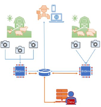
One of the fields of application in which Pistonhead has been adopted is Smart Farming. In Smart Farming, easily deployable devices need to be placed in special environments and are tasked with monitoring by performing measurements and analysis.
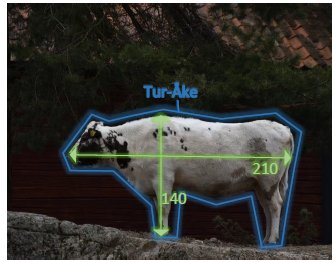
Here we would like to explore how a company working in the field of Smart Farming can use Pistonhead for the development of their applications. These take real-time measurements to provide farmers with the necessary information about the current status of their livestock, plants, and/or crops. In our example, Pistonhead is being used to monitor hogs or cattle, as illustrated in the figure above.
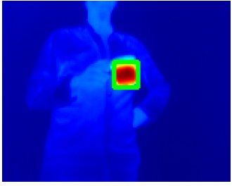
The health status of these animals can be measured in the infrared spectrum and evaluated through statistical analysis. The infrared part of the spectrum can be acquired through a Thermal Camera Module that has been used together with a daylight camera.
Simplifying Analysis
BitSim’s design handles the video and telemetry data and brings them into the ARM Processor System. The Linux system is customized to enable SPI and I2C interfaces directly in the User-Space. From the User- Space, communication is driven through C coded drivers. These drivers have been abstracted to one line of code through a Python wrapper. Finally, the company can analyse data in Python with PYNQ, OpenCV5 and other Python modules for numeric analysis and plotting.

The PYNQ framework
The main goal of PYNQ, Python Productivity for Zynq, is to make it easier for application developers to exploit the benefits of Xilinx FPGA SoCs performances and in particular the Zynq devices.
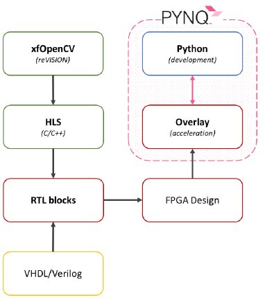
Python allows agile programming and can integrate many tools for Computer Vision, data analysis and visualization, such as: OpenCV, NumPy6 and Matplotlib7. While Python works at a high-level and offers fast development, the acceleration (overlay) is done at a low-level, meaning that it still requires skilled FPGA design engineers to create new accelerations. PYNQ can be divided into different layers, as shown in the image below; simplified, PYNQ is divided into two main levels: the Python level, for development and the Overlay level, for acceleration. An Overlay describes the PL design and is packaged in such a way that it can be easily loaded through Python. An overlay can be seen as a software library. Therefore, SW developers can work at the Python level, detaching themselves from the implementation of the Overlay, which involves knowledge of FPGA design.
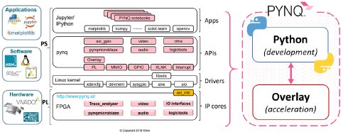
FPGA Acceleration in PYNQ
The Programming Logic (PL) part of the FPGA is configured through the loading of an Overlay in PYNQ. A short description of the methodologies involved in the creation of an Overlay is given here.
An Overlay is developed for the PL-part, meaning there is a description of how the physical FPGA resources are connected to each other. This also includes external interfaces from the FPGA to the HW (circuit board), the Pistonhead board in this case.
A PL design can be implemented with different tools and the workflow is given in the figure to the right. Each block signifies a tool. The blocks in the left column are used to generate blocks of code called RTL blocks. Application developers are using only the tools on the right (the PYNQ system). Colours identify blocks with some similarities.
An RTL block can be implemented in different ways: one option is using Hardware Description Languages (HDL) such as VHDL or Verilog. These languages offer deep control over block implementation, allowing the best performances with the minimum amount of FPGA resources. However, in-depth knowledge of FPGA architectures and device specific implementations are needed. This usually means development takes a longer time.
A second possibility is to implement an RTL block in C/C++. However, since this language has a higher level of abstraction, direct RTL implementation is not possible.
High-Level Synthesis (HLS) is used to compile C/C++ code into an RTL block. Compared to HDL, HLS offers faster time for development but less control over the end result. Moreover, C code has still to be structured in a low-abstraction way. Usually, HLS-designs work best with algorithms and image processing functions and less with control logic, like interfaces.
Targeting HLS development, Xilinx has released an environment for Computer Vision and Machine Learning development called the reVISION stack. This includes a range of development resources for vision systems like xfOpenCV, a library made for embedded vision inspired to the more known OpenCV.
To sum up:
- Software running on the PS can be accelerated
- Acceleration is done in the PL design. This can be implemented both in HDL (VHDL/Verilog) as well as in HLS (C/C++)
- The former offers full control over the actual implementation, but it also requires development times that can be much longer than HLS
- On top of HLS, it is possible to integrate CV oriented libraries like xfOpenCV (reVISION stack from Xilinx)
- Python can call accelerations which are packaged into an Overlay
In the appendix, we show an example of the Python code running on the Pistonhead board.
Productivity vs performance
This chapter has some technical parts, but the text has been written in such a way that everyone can understand the results and observations, even without a technical background.
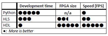
BitSim has taken an algorithm, used for scaling an image, called pyramiding, and implemented in both Python, HLS and HDL code. This allowed us to, to a certain extent, compare the three implementations and show the advantages and disadvantages of each. To make a fair assessment all three implementations have to be similar and hence use:
- A full-HD, grayscale image
- A gaussian blur with a 5x5 kernel
To simplify analysis, the time for data transfers to and from the blocks have been ignored.
We compared the implementations and scored them between 1 and 5 points. We were interested in the difference in development time: “How fast do I have a finished function?”, FPGA size: “How small is my design?” i.e. “Do I
need to buy a more expensive chip?” and latency: “How long does it take for the last pixel to be processed?”.
The numbers
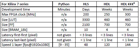
Although the scoring table gives a nice overview, some readers might be interested in the actual numbers behind the scores. These numbers require a more in-depth and technical description of the tests.
Pyramiding can be done on multiple layers, where each layer performs the same task, but takes as input the output of the previous layer. This means a two-layer blur result in an image that is blurrier than a one-layer blur.
The Python implementation, which makes use of the OpenCV library, is executed on the processor. This means two things:
- No FPGA resources are used.
- The speed depends on how busy the processor is.
Results in the Table show a reasonable variation of speed tested on a simple demo. However, speed might decrease depending from the complexity of your application.
The HLS implementation is using the OpenCV library from Xilinx. Such a library targets developers used to C/C++ programming which is more abstract and less restricted to specific platform. Nevertheless, a knowledge of embedded systems is still strongly required.
HLS comes with the advantage of making available a large stack of resources oriented to vision systems. As drawback, this stack of HLS resources can be harder to adjust if someone wants to increase performances or reduce resource utilization. Furthermore, HLS is meant to be used within a specific environment called SDSoC and it can be intricated to integrate the HLS libraries into a design or project.
The HDL implementation is hand-coded by BitSim engineers. The framerate is not impacted by the layers, instead the size is multiplied for each layer. This implementation also has little need for blanking, which also increases the possible framerates.
Our engineers have full control over the HDL implementation which can be optimized for each case and client respect to FPGA resources limitations and performance needs. This has a direct impact on the time for development.
Conclusions
Companies can run analysis by using the Pistonhead platform in their applications and collect useful data. The entire vision system can be developed fast and easy, directly on the HW-board and remotely be tested and revised. Bottlenecks and critical parts of the vision system can then be identified and successively accelerated in FPGA firmware to enhance and speed up the processing. New functionalities can also be integrated at any stage of development. If needed, only useful data can be sent out on the network.
How about the snakes?
Well have you seen a python? (there are 4)
How many other animals did you see?
www.bitsim.com
info@bitsim.com
1 Edge Computing puts processing closer to the data sources.
2 Hardware: everything that you can see and hold; Firmware: An FPGA configuration; Software: Program running on a CPU or GPU.
3 An optimized version of OpenCV for Xilinx.
4 MIPI CSI-2, a standardized high-speed Camera Serial Interface: www.mipi.org.
5 A common open-source library for Computer Vision.
6 A package for scientific computing.
7 A plotting library with similarities to MATLAB.
8 Faster FPGA speed-grade = more expensive silicon.
Appendix: Python coding examples
In the following example, we will show you how to acquire images from a IR1 camera and a daylight camera2 in Pistonhead board, the BitSims High-level imaging platform. For doing this, we will use BitSim libraries that simplify interactions with the cameras. Then, we will also apply some well-known image processing algorithms to the captured images. Everything, from the interface to the actual processing, runs on the board. To save space the images have been scaled to fit nicely on the pages.
Preparation
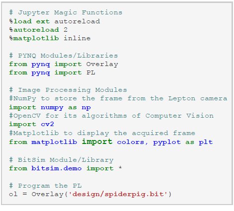
Before we can use the cameras, we need to set up the system. This means to import the Python modules (libraries) needed in the example and load the overlay.
Take images
Now we can use the both the cameras. We start with taking an image in the visible light spectrum.

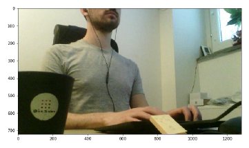
This gives us the following image of a BitSim engineer at work.
The second image is taken using the IR camera. You may observe that the image is not used immediately, it gets normalized first.
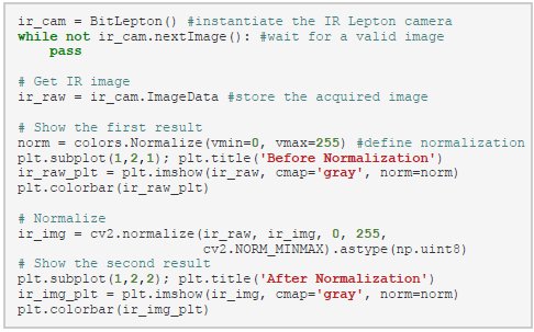
The first picture shows the image “as it is”: completely blank!3 The second picture shows instead the image after normalization: now it is understandable.
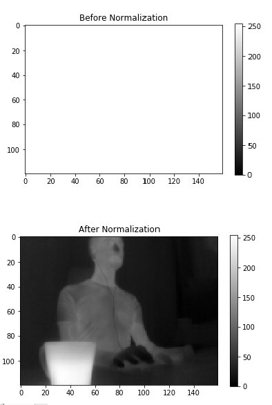
Image processing
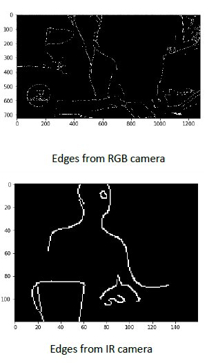
Now when we have the images, we can apply some image processing with OpenCV. In these simple examples, no accelerations are shown. An example of an image processing function is edge detection. Edge detection comes in many flavours, in our case we show the canny edge detection algorithm.
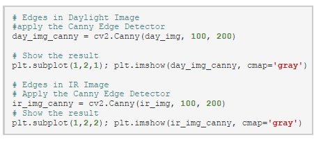
As the name suggests, edge detection shows the edges in the image.
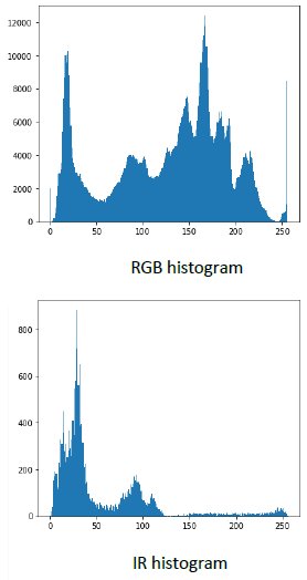
In image processing, generating histograms is an important operation. It can be used to select parameters for other functions and it can also show what is happening in an image.

In the histograms, we can see how many pixels of which value are in the image. The RGB image has been converted to greyscale to simplify the display. Although, it is not at all unusual to generate histograms for the red, green and blue channels separately.
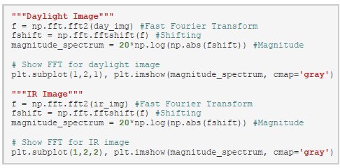
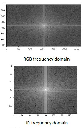
In this last example, a Fourier transform is done. This allows analysis in the frequency domain.
By looking at these plots, a human cannot see much. Further analysis on the data is needed to extract useful information.
1 A radiometric-capable compact IR (LWIR) camera solution from FLIR
2 OV5640 (OmniVision)
3 The values in the image before normalization are spread in a range between [-31000, +31000] so there is basically no information in the usual range [0, 255] and the picture results blank.
