Industry Articles
Setup Margin Aware Quick Hold Fixing-January 13, 2020 |
By Aishwary Dadheech, Technical Lead, Sandeep Jain, Technical Lead (eInfochips)
Static Timing Analysis (STA) is a key factor to validate while manufacturing a chip, where each design must go for setup and hold validation. In today’s era, technology nodes are shrinking and crosstalk plays a major role in timing along with cell-net delay. In addition, accounting derate (OCV/AOCV/POCV) is to overcome PVT uncertainties of the chip. As we move to lower technology nodes, we need more STA timing corner to validate the design.
In order to clean the setup/hold violation, multiple approaches are being used like changing VT, sizing cell, reducing crosstalk over the net, and so on.
Block owner should understand that:
- There are several timing corners, thus all unique paths should be taken into consideration.
- If the same path is reported in multiple scenarios, then applied fix should be based on the worst reported violation, hence it gets cleaned-up in all the scenarios.
Now, there are signoff tools which are efficient enough to optimize the design by applying a similar approach to reduce manual efforts, by using many inbuilt commands. In addition, we got DMSA (Distributed Multi Scenario Analysis) approach, which can optimize the reported timing violation for all given scenarios without impacting setup or hold. The only limitation is, as more scenarios are added into the consideration, more run time is required for the tool to generate timing ECO. Moreover, it requires extra licenses to be utilized, based on added scenarios. Therefore, the time of convergence plays a bigger role in this competitive market.
What if, we can get a similar fix without engaging much of signoff licenses, but in fewer seconds. In this article, we are going to suggest a very fast approach to improve reported hold violation of the design considering the setup margin.
Usual Hold Fixing Technique
It is always recommended to have what-if analysis for generating any Hold ECO. Produced ECO is important to be validated in the setup session to confirm that the given path does not violate setup. Additionally, the delay caused by added buffer should be estimated during hold analysis, this should be enough to avoid hold violations without causing any impact to the setup path. In general, a specific path should maintain required setup margin to accommodate delay cell for hold.
This manual approach is not helpful if the number of violating paths are more. Sometimes, for endpoints, setup margin is not enough; however, intermediate cells in the data path may have enough margin. Hence, considering these situations, cleaning hold violations can be a bit tricky, as the solution varies case by case.
The second approach is, DMSA. Running DMSA every time is also time/license consuming.
The Fundamental Approach
In STA, hold fails when the data reaches faster than arrival edge of the clock. To settle the violation, the data is required to be delayed at-least with the reported magnitude of the violation.
Addition of delay cells is the most traditional solution to get rid of timing. It is very crucial to select the appropriate timing point for delay cell addition. In case, provided timing point is also critical in setup path, then this could pop-up setup timing while applying hold fixes.
If we could identify the available setup margin for given points of reported timing paths, we can select specific timing point with enough setup margin (Margin should be enough to digest delay added for the hold). Choosing appropriate timing point with a good setup margin ensures a precise fix for Hold Violation and guarantees of not impacting setup timing.
Technique Detail
For each scenario, hold timing may differ in terms of failing endpoint and its count. Though unique paths should be listed and addressed solution should be appropriate enough to clean that specific path in all hold scenario.
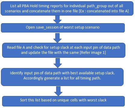
Let’s understand the fix with the suggested technique for one path_group violating in all scenarios.
Step 1]

Now, this file has all unique cells identified with the best setup slack for each path.
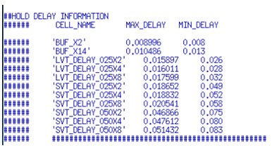
Step 2]

Based on this table add a suitable cell for selected cell pin chosen from step 1.
In case SETUP_MARGIN is not enough to accommodate delay cell for hold, then ECO for respective path should be discarded. As the setup is going to be critical into this path, it requires an individual’s attention to look for another/separate solution.

IMAGE1

IMAGE 2
Similarly, this method can be utilized for all violating path group. This method can be very well stated in a script. It requires one-time effort to incorporate the above technique in a script.
Once the script is generated, it takes very few seconds to create ECO. That is comparatively quicker than other traditional approaches.
This technique can be accepted for any design either block level design or for full chip design. We were able to deploy this approach on a latest 7nm technology project. With this utility, given hold timing is getting fixed in one iteration of the signoff cycle without imposing any effect on setup.
Major Advantages
- This method can be indispensable for quick timing closure.
- Saves signoff tool licenses and machine time.
- Avoids manual efforts of what-if analysis for producing ECO.
- It guarantees there is no influence on setup timing, as it maintain the setup margin before adding delay.
- Takes seconds to originate ECO for multi-scenario violations, compared to other usual methods.
Authors:
Aishwary Dadheech is a Technical Lead at eInfochips. He holds a Bachelor of Engineering degree in Electronics and Communication from SPSU, Udaipur, India and possesses over 6.10 years of experience in lower technology node for complex networking SoCs. He has developed expertise in PnR, static timing analysis and power optimization.
Sandeep Jain is a Technical Lead at eInfochips. He holds a Bachelor of Engineering degree in Electronics and Communication from Govt Engineering College, Ajmer, India. With over 6 years of experience in physical designing, he has developed expertise in PnR, physical verification, static timing analysis.
