By Himanshu Bansal
1. INTRODUCTION:
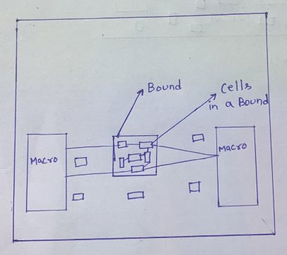
A placement bound is a constraint that controls the placement of groups of leaf cells and hierarchical cells. It allows us to group the cells and minimize the wire length. It helps us to place the cells at the most appropriate location.
Many Industries are using this concept, As this can help to reduce the timing for sure. But many scenarios have to be taken into considerations to make a bound. If the conditions are not fulfilled then it can affect other things and may violate the timing and make it more worst then before. I'm discussing those scenarios in this paper. Before making the bound check the timing margin, If it could be possible to make it nearby zero (Or upto the margin what so ever is needed) by other methods then try them first, Because bounds can consume more time. We look forward and seeing what our industry creates next to overcome with this problem.
2. OBJECTIVE:
The main objective of the bounds in placement is to minimize the timing of the extremely timing critical paths.
There are two different types of bounds:
- Move Bounds: It restricts the placement of the cells to the specific location of the design area.
- Group Bounds: These are floating region constraints. Cells in the same group bound are placed within a specified bound but the absolute coordinates are not fixed. Instead, these are optimized by the placer.
2. HOW TO CREATE A BOUND:
To create a bound we use create_bounds command. This command allows us to define region-based placement constraints for coarse placement. The bounds which are created by this command once, do not need to re-created when the design is reloaded.
We have various syntax of create_bounds command:
[name bound_name]
[-coordinate {llx1 lly1 urx1 ury1 …}]
[-dimension {width height}]
[-effort low | medium | high | ultra]
[-type soft | hard ]
[-exclusive]
[-color range_0_to_63]
[-cycle_color]
object_list
CELLS TO INCLUDE IN A BOUND:
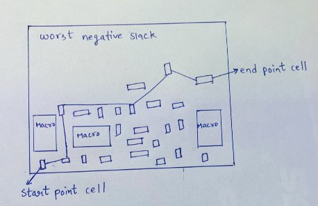
Generally, The cells which are coming in the path of Worst Negative Slack of the design will come under the bound. These are the most violating paths of the design in terms of timing. There could more than one bound in a design, It depends on the paths which are violating the timing of the design. After highlighting these paths, We’re checking the Startpoint and Endpoint of those paths. To create a bound, We’ll only consider those cells from that Startpoint and Endpoint which will not violate the timing of their own endpoint cells.
(Note. The cell which is coming in the bound has became the new startpoint and it has its own endpoint as well. If we want to consider this cell into the bound then we’ve to check the slack of this path. If the path has positive slack and the slack margin is good enough, then we can consider this cell into the bound and if not then we’ll not consider it.)

Ex. create_bounds -name “temp” -coordinate {100 100 200 200} INST_1
The above example creates a bound with a name “temp” and constraints the placement of the INST_1 instance to lie within the rectangle. The rectangle has its coordinates {100 100 200 200} which means its lower-left corner at {100 100} and upper-right corner at {200 200}.
As we know, there are two types of bounds: Move bound and Group bound.
If we use -coordinate option in create_bounds, then the tool will create a move bound. If we use -dimension option, then the tool will create group bound with a given bounding box. And if we do not use any of these options then the tool creates a group bound with a bounding box and the size of the bounding box will be computed internally by the tool. Then in this case we have to use -effort option in create_bounds to specify the effort level either soft or medium or high or ultra. This option is used to bring the cells closer. According to the necessity we can specify the effort level.
We have -types option in which soft and hard bounds are given. Soft bound is the default option of the tool, with no guarantee that the cells will be places in the bound or not. Hard bounds force placement of the specified cells inside the bound. It may happen that other cells can also come inside that bound in hard bound. This is a hard constraint for the tool and this renunciates other objectives also like timing and routability. In -exclusive option, It force the placement of the specified cells inside the bound. All other cells must be kept outside the bound, only the cells which are specified will come inside the bound.
The -color range_0_to_63 option will specify the color of the move bound in the range of 0 to 63. The default is no_color. The -cycle_color option will allow the tool to automatically assign the color.
HOW TO DECIDE THE LOCATION OF THE BOUND:
To find the exact location of the bound in one time is quiet difficult. So this might take number of iterations to find the exact location. We will check the timings by placing the bound in appropriate position and then slightly move it. Then observe the difference in the timings. Whenever the timing meets, then we’ll stick to that position and place the bound. The slack of the input to register path and register to output path has also to be checked. This helps us to fetch some gain from the margin available to move a bound.

HOW TO DECIDE THE SIZE OF THE BOUND:
To decide the size of the bound, First we have to decide the cells which needs to be pulled inside the bound. After deciding, Calculate the total area of the cells. We can find the area of the cell either by specific command of the tool or from the reports. According to the area of the cells, the total area of the bound would be decided. Here is one more factor which has to be taken into consideration that is the slack margin. If enough margin is not available into the previous path and next path of the cell, then we cannot pull that cell into the bound because of the larger distance. To overcome from this problem, we have to take bigger size of bound comparatively to the area of the cells we’ve calculated.

Q. Why the cells are setting apart in placement stage ? Is placement tool is not optimizing it properly ?
Ans. The cells are setting apart in placement stage due to some reasons, these are:
-
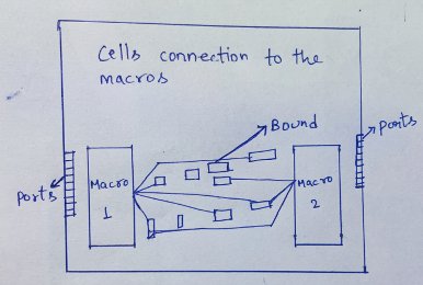
Floorplan: According to the techniques used in the floorplan to place macros, We've set the macros apart because of any reason either because of ports communication with macros, or macro to macro communication, or because of any constraints. These are the macros whose registers are talking to each macro but due to above reasons we've set those apart. So, in placement stage we can see those registers are setting apart as well.
-
Some tight constraints: So, This is another reason as well. There are some constraints which affects the registers to setting apart. Some tight constraints like: Multicycle paths, Uncertinity, or some others also. We can find about these constraints in SDC file.
The placement tool is optimizing it properly.
Q. How Bounds can help in placement stage ?
Ans. As we've discussed earlier, Bounds helps us to reduce the timing factor from the design as per the need. But bounds is the later option used for the reduction of the timing. First we go with the changing of our Floorplan, By adjusting the macros. Bounds help in reducing the wire length and grouping of the cells. It can helps us in minimizing the timing critical paths.
SOME MORE COMMANDS RELATED TO BOUNDS:
- update_bounds: It will update an existing bound. It can add or remove objects from it. The bound must be a type of move bound.
- report_bounds: It will report the bounds in the design that were created by the command create_bounds. Bounds from an input PDEF file are not reported by this command.
- get_bounds: It will create a collection of bounds in a current design that match certain criteria. The command returns a collection handle (identifier) if any bounds match the patterns value and passes the filter, if specified. If no objects match the criteria, the command returns an empty string.
- remove_bounds: This command removes bounds constraints from the current design.
Conclusion:
In this paper, We've discussed all about bounds. The location, size, what cells to include in a bound and so on. VLSI Industries are using this concept in many ways. Trainee engineers are also using this concept during their demo project. This concept is very much useful. But now a days, these concepts are tending towards their limitations, but Companies are working on this and coming up with potential solutions which include relavent modifications.
References:
-
Physical Design Complete Book.
-
J.Bhasker, Rakesh Chadha, (2009) static timing analysis for nanometer designs, Springer.
-
IC Compiler Commands - Version C-2009.06, June 2009.
-
IC Compiler Implementation User guide - Version J-2014.09-SP4, March 2015.
