by Richard Pugh, Neill Mullinger, Jay Hopkins
Synopsys, Inc.
Hillsboro, OR USA
Abstract:
This paper illustrates the challenges facing design and verification engineers developing next generation products and systems. Increasing design size and complexity are forcing a transformation of verification methodologies to adequately test these new products. This transformation is to higher levels of abstraction in test bench languages and verification IP, enabling the creation of smarter test benches. It is being led by verification models that have capability beyond traditional bus functional models and can be used with a variety of test bench languages. Models also vastly reduce the time to first test within a high-level test bench. The new DesignWare Verification Suites provide a host of features and functionality that enable verification engineers to create powerful test benches that are adaptive and reactive. Features like constrained random stimulus generation and programmable coverage points reduce the burden of the verification engineer allowing for the fast and efficient creation of sophisticated test benches. The models also enable a more realistic way of driving stimulus into the design-under-test by providing random data generation capabilities. This simplifies the job of the verification engineer and enables them to quickly complete the verification task.
Introduction
Today’s IC and System-on-Chip (SoC) design trends have placed an immense burden on the shoulders of verification engineers. Processor complexity, custom logic size, software content, and system performance are all increasing at the same time that schedules are being squeezed and resources are stretched. The now-famous Collett study shows that 70% of project effort for complex ICs is spent on verification. Not surprisingly, project teams are looking for more effective methods to verify their designs.
Verification engineers are consequently looking towards new methodologies to reduce test bench development time, and speed-up the time it takes to achieve complete verification of their ASIC or SoC. Directed tests and ‘golden’ reference files will soon become the primitive tools of the modern test environment.
Constrained random test methodologies allow engineers to rapidly test their designs across a range of parameters and assist in creating test benches that are adaptive and reactive. Instead of specifying each individual event to exercise the design, the engineer specifies ranges, within which the test bench then exercises the target device. Feedback from monitors and models identify test suite hits and allows the test bench to adapt and check new areas. This new functionality in the models replaces much of the effort associated with manually creating vectors to accurately reflect system behavior. Constrained, randomly generated vectors are much more likely to hit corner cases in the design.
Designers are also migrating towards the use of industry standard buses to improve re-use, interoperability and broaden market opportunity. This creates an additional burden on verification engineers to test that designs meet conformance and are interoperable with other modules and designs that use the same standard.
Smart verification models not only save an enormous amount of test bench development effort, but begins to move the verification engineer towards higher-level test bench functionality with constrained random test verification methodologies.
Couple smart verification models with hardware verification languages (HVL) and you take the next step beyond traditional HDL-based verification into self-checking, automated test benches. Object-oriented HVL's give verification engineers features and capabilities above that of traditional HDL's. HVL's provide functional coverage analysis, random stimulus generation, property verification, data and temporal checkers. Leveraging this pre-built test bench functionality of the HVL's in conjuction with smart verification models that provide the IP-specific behavior and functionality arms the verification engineer with the tools needed to quickly generate test benches and thoroughly test the design.
Role of Smart Verification Models
The first commercial verification components became widely available in the mid-1980’s, driven by a need for full-functional models used in board-level verification. They included full functional microprocessors that executed microcode, but suffered from serious performance limitations. Over time it became apparent that higher levels of abstraction were needed to deliver the required performance. Consequently, bus functional models were developed that were accurate at the boundary of the component and were driven by commands from the user rather than through the execution of software instructions. These models ran an order of magnitude faster than full functional models and have been used now for many years to exercise system behaviour.
This same method was applied to the creation of bus models that stimulate and respond to transactions on the bus. They allow ASIC verification engineers to mimic bus behaviour and verify that a design interface will communicate to the rest of the system, while keeping simulation performance high. Monitors check for protocol violations and give feedback on coverage. PCI, PCI-X, USB and Ethernet are some of the most widely used of these models.
Today’s modules, components and systems can process massive volumes of data. This is creating a need for faster, more effective data communication and is driving a new set of more complex, faster buses, like AMBATM, CoreConnectTM, RapidIOTM, PCI ExpressTM, HyperTransportTM, 10G Ethernet, and so on. The complexity of these protocols has increased to include a huge number of conditions and states, rendering directed testing alone insufficient. Creating a test suite for these protocols is a major effort that detracts from the primary need to verify custom logic and system behavior.
To solve this problem, bus protocol models are now evolving to yet higher levels of abstraction that include constrained random test methodologies, typically found in high-level verification languages. The new enhanced verification models use their protocol knowledge to drive transactions onto the bus within the user defined application specific needs of the design. They allow engineers to build adaptive, reactive test benches that preclude the drudgery of directed tests and hard-to-maintain ‘golden’ reference files. Creating a test suite now becomes significantly simpler for verification engineers who don’t need to spend time learning the details of the protocol and weeks or months writing a directed test suite. The advantage of using these enhanced models is immense from the simplified usage and improved coverage.
Methodology
In the case of a bus standard like AMBAâ„¢ (Advanced Microcontroller Bus Architecture), that has a master and slave topology, the engineer can easily create a virtual system of multiple masters and slaves that mimics the behavior of the system into which the device under test will eventually plug. Instead of writing many hundreds of specific commands that drive specific transactions onto the bus at specific times, a series of constraints are developed. These configure the master to behave within the confines of the master device that will eventually be used in the system. The master then generates transactions onto the bus using data from one of a variety of possible sources. The master essentially acts as a data pump that initiates activity on the bus within the relevant confines of the system. Weights can be applied to bias the transactions towards the behavior of the actual system. Slave devices can similarly be configured to respond in a constrained, random, weighted fashion to the transactions that are initiated by the master. System behavior can be explored by changing the weights of the response, resulting in a realistically driven system.
Monitors watch for protocol violations, log transactions and provide coverage statistics. An application programming interface (API) allows dynamic access from the test bench to check for specific coverage points. The new monitors can be programmed to look for specific sequences of transactions that are added to the coverage list. Within a sequence of transactions can be a choice. For example the monitor may look for an incremental burst, followed by an OKAY or a SPLIT, followed by a burst from a different master. This would then be logged as a coverage “hitâ€.
All models and monitors give asynchronous notifications to the test bench allowing continual feedback that enables reactive behavior in the test bench.
This functionality is typically available today for users of high-level verification languages such as OpenVeraTM. The new smart Verification Suites that have been developed by Synopsys® are designed to bring constrained random functionality to users of any verification environment.
A Design Example with AMBA
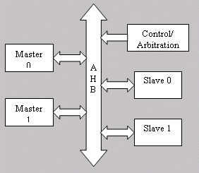
To illustrate this, let's take a real world look at why verification requirements are changing with the complexity of the systems being designed today. The design is an AMBA-based design commonly used in system-on-chips today. The AMBA bus has a high-speed main processor (AHB) bus and a low-speed peripheral bus (APB) that is connected to the AHB by a bridge. There is arbitration and control logic for the bus. The AHB can support multiple master and slave blocks and the APB supports multiple slave devices. This is common among today's new bus designs but adds complexity to the verification task. Now complex interaction and data flow between the devices must be modeled and verified.

Figure 1.
The example design, see Figure 1, consists of two AHB master devices that communicate with two AHB slave devices. Just focusing in on the slave devices, there are four types of responses possible that the slave can send to the master: OKAY, SPLIT, RETRY and ERROR. In addition to the responses, there are N number of wait states that the slave device can issue while performing a request. Multiply this by two slaves and there are a large number of potential states and sequences that need to be accounted for during verification. Using standard HDL test bench techniques would not be practical for providing sufficient coverage. Enter constrained random testing (CRT). CRT capabilities enable the verification engineer to quickly and efficiently create a very complex test environment to thoroughly test the arbitration and control logic. CRT augments the traditional techniques used to validate basic functionality, i.e., checking the address mapping, walking one's and zero's, reading and writing patterns to memory. The goal of these new advanced features is to shift the cycles spent on verification from test bench creation to simulation verification time. In the example design, the goal is to verify the arbitration and control logic under a variety of conditions and loading. Given the potential number of states and transactions, directed testing is not a viable option for verifying the design.
The models need to be configured to automatically respond to the control and data applied by the rest of the design or to generate transactions for the design. Focusing on the master devices, the steps required to configure the master device are:
- Define a transaction generator
- Specify the type of transaction, random weighting, wait states, address range and payload data
- Assign the transaction generator to a master device in the simulation
- Attach a payload to the source
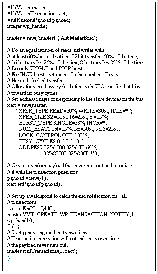
In four steps, an AHB master device can be programmed to generate stimulus for the simulation. Figure 2 shows example code that a verification engineer would use to configure and program an AHB master device for random stimulus generation in the test bench. Just ten lines of code per device configure the master to generate random AHB transactions.
When simulation starts, the master will be configured to generate transactions according to the constraints given. It will continue to generate transactions this way until one of three things happens: the simulation is terminated, the payload is exhausted or the user loads a new configuration into the master device. This aspect highlights the possibilities for self-checking, intelligent test benches.
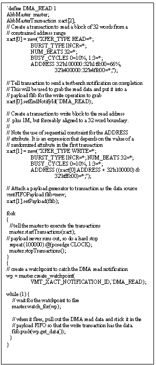
Figure 3 shows an example of setting up the AHB master to perform aligned DMA transfers between devices on the AHB bus. In this case, once the reading of data is complete, the test bench is notified that the read completed and then takes the data and uses it as the payload for the write portion of the DMA. It is easy to see that this data block can also be passed to the slave receiving the data to validate that the write occurred correctly. One other feature highlighted in Figure 3 is the ability to build a new constraint that is dependent on a previous one. This technique is called sequential constraints. In the aligned DMA transfer, the read transaction address is used as the base address for the write transaction. The address for the write transaction is offset by 1M and aligned to a 32-word boundary.

Figure 2.
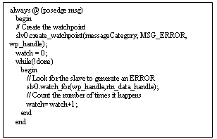
Another element shown in Figure 3 is the watchpoint. Watchpoints and the watch_for command are key enablers in facilitating self-checking test benches. A watchpoint will watch for the event specified to occur and will return a handle to the test bench to indicate that the event has triggered. Watchpoints can be of the one-shot variety or they can trigger every time the event occurs. Elsewhere in the test bench is a watch_for command that looks for the handle that the watchpoint will pass to it when triggered. With the watchpoint enabled and the watch_for command in the test bench, the test bench is ready to respond to the condition or event of interest and act accordingly. Figure 4 shows an example of a simple watchpoint and code in the test bench that counts the number of times the watch point is triggered.

Figure 3.
While these transactions are occurring on the bus, protocol monitors check and record the transaction events. Protocol monitors are used to track compliance to the AMBA transaction protocol for either the AHB or APB bus and provide coverage information that can be used by the test bench to adjust the test bench while the simulation is running. The monitor is connected to the AHB bus and "snoops" the traffic on the control, data and address portions of the bus. The monitors have commands associated with them that allow the test bench to query the coverage bins in the monitor. The test bench can then decide how the testing is proceeding and make adjustments to the transaction generation characteristics of the master device or the response characteristics of the slave devices in the simulation. Coverage points that are checked are transfer type, transfer size, HTRANS status, arbitration status, and protocol/control errors.

Figure 4.
Constrained random test capabilities coupled with advanced analysis features like watchpoints and coverage metrics allow for the creation of self-checking test benches. This new generation of verification models brings advanced test bench capabilities to all designs, Verilog- or VHDL-based, and operates with their test bench language of choice: Verilog, VHDL or OpenVera. The verification model is a protocol IP block for the test bench. Test bench functionality is incorporated into the behavior of the model and the model can act as interrupt mechanism into the test bench.
The real value of these new verification models is what they do for the verification engineer. The models allow the verification engineer to quickly create sophisticated, self-checking test benches for the system under test. Configuring the models to generate/respond in a constrained and random way can be accomplished in a short amount of time enabling the verification task to be started sooner in the verification process. More time is spent in simulation as a result of the reduction in the time it takes to create the test bench. Using constrained random transactions fed by various sources (random, test bench generated, application-specific) exercises the system in a more realistic way and translates into more scenarios being covered.
Summary
Synopsys bus protocol models can save months of time in the development of a test bench environment. Verification engineers using any language can gain access to constrained random technology, leading to more effective system verification. Synopsys models do not force a major change of methodology; they can be used for both directed and randomized testing. Synopsys bus protocol models have been successfully used and proven on hundreds of designs. These models are included in the DesignWare Library and the DesignWare ASIC Regression Library.
Synopsys and DesignWare are registered trademarks of Synopsys, Inc. OpenVera is a trademark of Synopsys, Inc. All other brands, products or service names mentioned herein are trademarks of their respective holders and should be treated as such.
