by Achutha Jois (achutha@sasken.com) and Vishal Dalal (vishald@sasken.com)
Sasken Communication Technologies Limited,
Semiconductor Division, Bangalore,
Karnataka, INDIA
Abstract
Verification is no longer merely a testing effort, it is also designing a verification environment. SoC design can said to be interconnection of IP’s, likewise SoC verification is interconnection of verification IP’s. Hence in this paper we emphasis more on problems in SoC verification and how some of the problems can be solved with the help of reusability and modularity. This paper also shows a detailed description of verification environment and how it could look like.
Introduction
The complexity in present day SoCs is increasing tremendously with more and more IP’s put on a single piece of silicon. The revolutions in fabrication technology have enabled integration of hitherto discrete system components on to a single piece of silicon. SoC revolution is one such kind. The life span of a product, time to market constraint and availability of many such discrete components as an individual product or IP’s in market has considerably reduced the design cycle of a SoC, so is SoC verification.
In SoC verification, there are mainly three C’s that dominate the complete verification. These three C’s are Connectivity, Controllability and Coverage.
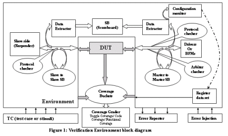
In this paper we will explain verification approaches, three C’s of SoC verification and verification environment as shown in Figure 1. We will analyze the usefulness of reusability and modularity in SoC verification and how they help tremendously in verification.
Looking for a good verification approach
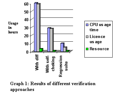
Verification started with visual inspection or sanity checks, which were good for only small designs. Doing them for every stages of design was a tedious job and also creates variance in verification. They also resulted in manual errors; CPU and license time gets enormously wasted as referred in Graph 1. Therefore this process must be automated.
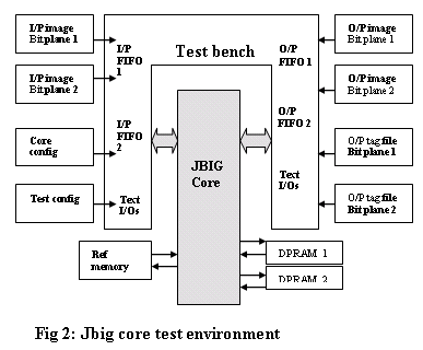
The next step towards solving some of the above stated problems is golden reference comparison. Consider the JBIG core test environment as shown in Figure 2, the output images needs to be compared after decoding with raw image, Using UNIX “diff†capability we can do the same. An example is shown below:
diff output_images/ jbig_dec_img7_multi_2bp_auto_fifo_1_out_jbig.txt raw_images/image7_multi.hdl >output_images/jbig_dec_img7_multi_2bp_auto_diff1
diff output_images/jbig_dec_img7_multi_2bp_auto_ fifo_2_out_jbig.txt raw_images/image7_multi.hdl >output_images/jbig_dec_img7_multi_2bp_auto_diff2
But still “diff†has it’s own disadvantages, mainly it still needed manual attention, CPU and license usage time was enormous as referred in Graph1.
The next steps towards achieving better results were Automated self-checking test benches proven by Graph 1. An example below shows how exactly that can be done.
entity jbig_dec_core_tb isgeneric(
jbig_core_cnfg : string :="";
jbig_dec_core_test_cnfg : string :="";
in_jbig_f1 : string :="";
in_jbig_f2 : string :="";
fifo_1_out_jbig : string :="";
tag_fifo_1_out_jbig : string :="";
fifo_2_out_jbig : string :="";
tag_fifo_2_out_jbig : string :="";
tb_multi_image_generic : boolean:= false
);
Above few generic switches are declared, By using these generics we can achieve simple automation. By passing on the value for the generic while loading RTL on to the simulator as mentioned in the simulator command, we can achieve the same.
architecture test of jbig_dec_core_tb isbegin
tb_multi_image_set:
if (tb_multi_image_generic = TRUE) generate
tb_multi_image <= '1';
end generate tb_multi_image_set;
core_cnfg: process
file Reg_file : text is jbig_core_cnfg;
begin
file_open (Reg_file, jbig_core_cnfg,READ_MODE);
end process core_cnfg;
end test;
Simulator command:
ncelab work.jbig_dec_core_tb:test -access +rw -generic 'jbig_core_cnfg=>"core_cnfg/image7_core_cnfg.txt"'-generic 'jbig_dec_core_test_cnfg=>" test_cnfg/ jbig_dec_
-generic 'tb_multi_image_generic=>"TRUE"'
ncsim work.jbig_dec_core_tb:test -input sim_verilog -input jbig_dec_img7_multi_2bp_auto.args -update
The above simple example shows how automation can be easily achieved with generics in VHDL or parameters and ifdef in Verilog, and exploring possibilities of compiler and simulators.
A configurable self-checking test bench was the next step forward. Monitoring multiple possible operations simultaneously helped a lot to improve the verification. To achieve good coverage scripting languages were used or coverage tools are good guides to benchmark against a predefined goal. But to achieve full coverage, random and directed random approach is essential.
Summarizing all the above stated problems, the needs of the hour are:
(a). Very good verification environment,(b). Coverage driven test cases and
(c). Regression suite.
The graph 1 is a classic example how drastically we can improve the performance.
The complexity associated with a SoC verification demands very stable and consistent verification environment. It also requires faster simulators and higher degree of automation. The verification environment shown in Figure1 is one such kind of environment.
The C’s of SoC verification
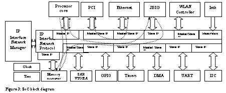
As mentioned earlier, the three C’s that dominate SoC verification are Connectivity, Controllability and Coverage. We can define Inter-connectivity, as the Inter-communication ability of IP’s to correctly communicate with other and communicate with the processor core. For example, in the Figure3, the reads and writes from/to memory are done through memory manager block, Checking for data drops, protocol checks, arbitration checks, similarly checking for inter-communication between different IP’s inside SoC through IP interface network protocol bridges, ensures connectivity.
The second C in SoC verification is the controllability. We define the controllability as the ability of master to have complete control over its slave. The major task here is to verify if a master can configure the slave as per its requirement and to also verify the slave request mechanism.
This brings us to the third and final C in SoC verification, Coverage. Functional and code coverage are the two main part of the third C. Coverage indicates the effectiveness of our testcases. Coverage is a goal to measure the quality of verification. Functional matrix derived from specification of the chip is very important in getting a very good coverage. The features of the design hit by various testcases are indicative of the functional coverage. A simple perl script also can do the job in the case of a small design, or tools like specman elite can also help to get a good coverage report. Code coverage can be done with options provided in the simulators like Modelsim from Model Technology or Ncsim from Cadence Design Systems, INC or with the help of tools like Vnavigator from TransEDA.
Problems in SoC verification
The number of gates that can be accommodated inside silicon is rapidly increasing according to technology evolution in accordance with Moore’s law. The complexity of the chip is also increasing tremendously, So designers have the flexibility in putting more and more logic inside a chip and today we have revolution such as SoC.
Due to complexity of the SoC, Verification is becoming really very hard. To verify the SoC Multi-dimensional technical skills are needed, old aged simulators are not enough as the simulation time is enormous, verification approaches seem very bleak, time to market is shrinking, derivative and verification cycle are decreasing. Therefore SoC verification is very challenging.
Looking for a good verification tool
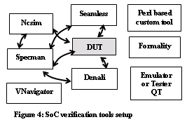
Tools such as Vera from Synopsys, INC and Specman Elite from Verisity, INC and for Co-verification Seamless from Mentor Graphics, INC would be a good choice.
Considering the widespread usage of OOPS concept in verification and similarity of the e-Language by Verisity, INC with c-Language. E-Language (verification language) with the help of verification advisor supported by Verisity, INC would make a good choice for SoC verification. Functional coverage by the tool Specman Elite looks very powerful. Figure 4 shows a classic example how a SoC verification tools setup could be.
Need for good SoC verification environment
Lessons learnt from our previous project reveal the following observations, considerable amount of time is taken to develop the verification environment and in the same process fix the e-code bugs. The e-code bugs were because of the tight coupling between all the modules of the verification environment, or every time we try to do any further development to the environment, we used to break the whole environment and affect others work also. In order to sort out this problem, we introduced Revision control system, assuming it will solve many of our problems, but invain they really did not solve all our problems because strategic verification path was very shaky.
Moving forward for the next project our strategy regarding the verification was pretty clear. We planned the whole environment well in advance, as to how it should look like and what are all the minute components of it. And also how much effort needs to be put into testing the real RTL and effort to develop the whole environment, We had a separate dedicated resource for both developing verification environment and test.
Reusability and modularity key to SoC verification
Reusable IP brings experience in the process, tools, technology and high productivity, being proven in the past is one major influencing factor. How modularity helps in reuse is proven with the help of simple examples in the coming sections. If the verification components are modular and are reused, high functional coverage can be expected. As the components are re-used verification can be directed more towards specific corner cases yielding high functional coverage.
An IP can be used in different types of SoCs. These suggest that the verification components can also be reused with minor changes. These days great amount of effort is spent to create a verification environment, which can be easily reused. The verification IP’s are therefore in high demand to ease the increasingly complex SoC verification.
The success of verification depends to a great extent on stability and effectiveness of verification environment. If the verification environment is reusable then it may reduce the verification efforts to a great extent. It requires that the verification components are highly modular.
There are methodologies for example eRM (e Reuse methodology, [7]) that helps in building the reusable verification components. It defines three main requirements for reusability:
• Least interference between verification components (coexistence)
• Common look and feel (commonality)
• Combining multiple components for synchronized operation (co-operation)
Planning for verification environment
Our major goal was to achieve reusability in our verification environment, after learning from experiences in the past. Along with project plan plus the test plan, we had another document to show the management, a Verification environment plan. Our verification environment had the basic block diagram as shown in Fig1. The major components in our environment were:
1. Scoreboard: Master to Master, Master to Slave, Slave to Slave.2. Protocol checkers and protocol monitors
3. Arbiter checkers
4. BFMs, drivers and Initiators.
5. Data extractors or collectors
6. Responder, e-models or e-memory models.
7. Coverage bucket and coverage grader
8. Register data set.
Importance of Modularity
Let us take an example, it shows how we started coding the scoreboard (please note here we are using e-language to code). E.g.1:
Scoreboard:wait until (‘top.address_strobe’ == ‘0’);
addr = ‘top.addr’;
wait until (‘top.data_strobe’ == ‘0’);
data = ‘top.data’;
emit event_data_extracted;
fetch_data_from_internal_memory (addr, return_data);
if (addr = return_data) then {
print (“data check for addr passedâ€); };
else {dut_error (“data check failed for address);};};
expect (‘top.address_strobe’ == ‘1’ and ‘top.data_strobe’ == ‘1’)
else dut_error (“protocol errorâ€);
From the above example, it is very clear that data extracting, protocol checking and scoreboard mechanism are embedded inside one unit. Modularity is totally lost and can we reuse the same component when the protocol changes or if there is a change in the way you capture the data?
Consider the example below, e.g.2:
Data extractor:wait until @event_strobe;
addr = ‘top.addr’;
wait until @event_data_capture;
data = ‘top.data’;
emit event_data_extracted;
Scoreboard:
wait until event_data_extracted;
fetch_data_from_internal_memory (addr, return_data);
if (addr = return_data) then {
print (“data check for addr passedâ€); };
else {dut_error (“data check failed for address);};};
Protocol checker:
wait until (‘top.address_strobe’ == ‘0’);
wait until @event_strobe;
wait until (‘top.data_strobe’ == ‘0’);
wait until @event_data_capture;
expect (‘top.address_strobe’ == ‘1’ and ‘top.data_strobe’ == ‘1’)
else dut_error (“protocol errorâ€);
In the example 2, we can clearly see the difference between data extractor, protocol checker and scoreboard. All the components are independent of each other, it observes the modularity and reusability concept. We can reuse the protocol checker wherever the particular way of protocol checking is needed. The same thing applies to data extracting and scoreboard.
Minimizing the effort spent on verification
We targeted mainly the duplication of work, like previously each module level test owners used to have their own verification components, we analyzed all the modules and listed out the common components which can be developed by a single resource and the module owners can concentrate on the their tasks. So here we proved that proper management of reusability saved us a lot of time.
Effective testing
The effort of the test team narrowed down to finding bugs rather than fixing the problems of environment or developing new verification component. The test team was able to do their work at high efficiency as they need not have to concentrate on the e-language or the OOPS concept which was needed to develop the whole environment. The productivity or the utilization factor of the whole verification team improved as the whole effort was well divided and concentrated.
Creating Reusable Verification IP’s
On the other hand we were able to fine-tune our verification component, as verification IP’s which can be reused in future verifications. Later we have plans to convert the same as eVC (e Verification Components).
Right levels of abstraction a key to modularity and reusability
When porting from module level environment to top-level environment, how best the verification components can be reused, how fast we can port the environment with out breaking the top level environment, depends upon how we chose the abstraction level.
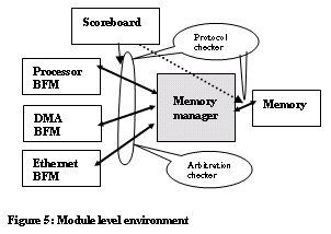
The amount of rework needed to port should be very minimal. Tight coupling and inter-dependency between the verification components plays a crucial role in deciding how much effort needs to be put.
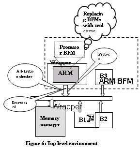
Consider the example shown in figure 5, When we start porting to the top-level environment, one of the problems we face is abstraction level. Figure 6 shows the top-level environment.
Hardware - Software Co-Verification.
The software is an inevitable component of a SoC. The correct working of SoC is possible only if Hardware and Software are correctly integrated. We therefore need to verify both of them together. This suggests application of methods like Hardware-Software co-verification where software component of a SoC is run on the simulated hardware (virtual prototyping).
The HW-SW co-verification methodology enables integration of HW-SW. This method of virtual prototyping enables verifying HW-SW as a SoC system component. It can give high amount of modularity and hence reusability to verification. Figure4 shows one such tools setup.
The HW component will drive the design simulating on HW simulator. It will directly stimulate the design with generated test stimulus, verify the functional correctness or checking and generate the coverage reports based on the features of the design covered by the test cases.
The integration of HW-SW makes the environment modular and reusable, also makes it faster, avoids expensive hardware changes later and improves the quality of verification.
Conclusions
In this paper we have analyzed the problems faced in today’s SoC verification, discussed about three C’s of SoC verification, we analyzed how reusability and modularity can drastically reduce the verification effort if followed with a proper methodology.
We reached our target much ahead of schedule by following guidelines mentioned in this paper.
We have the following conclusions:1. A good verification environment helps in faster verification while checking the completeness of the design.
2. Right approach will always yield in higher throughput.
3. Reusability and Modularity in multimillion-gate SoC design verification is very much essential.
4. Achieve Time to market with reusability and modularity.
Acknowledgements
The authors wish to thank Anantha Kinnal, Nagendran Gunasekar, Mohamed Imtiaz, Vinay Hebballi and Sachindranath for their valuable suggestion. The authors would also like to thank Veeraiah Chowdary and Hanumesh purohith for allowing us to mention the test setup for JBIG IP.
1) Verisity’s “verification Advisor†version 3.3.4, Oct-15-2001, Verisity design Inc, USA.
2) System-On-Chip verification, Methodology and Techniques by Prakash Rashinkar, peter Paterson and Leena Singh, Cadence Design Systems, Inc.2001.
3) Writing Testbenches, Functional verification of HDL models by Janick Bergeron, Quails design corporation.2000.
4) Achutha Jois’s “Specman based verification over traditional â€, Sasken communication technologies, Internal documentation, Bangalore, India. Nov 2001.
5) A complete SoC verification framework accelerating productivity through reuse and automation by Bernd stohr, Michel Simmons, Joachim Geishauser, Motorola, Munich, Germany.
6) “System level verification of present day SoCsâ€, Vishal Dalal, 6th IEEE VLSI Design and Test Workshops, August 29-31, Bangalore, Karnataka, INDIA.
7) “Verification Reuse Methodologyâ€, White paper at www.verisity.com
