By Darshan Talati, eInfochips
Introduction
Any hardware that is to be installed in an aerospace system must undergo the DO-160 qualification testing. The DO-160 qualification testing includes different environmental conditions and test procedures like temperature, humidity, vibration, waterproofness, fluid susceptibility, fungus resistance, shock and crash, RF emission, and so on.
Hardware is made up of processors/controllers, memory, and different input/output peripherals. Each of these hardware must go through the DO-160 qualification before it is installed in an aircraft.
Any hardware undergoing the DO-160 qualification must test all interfaces of data communication that provide inputs and outputs from the hardware.
In this article, we will focus on software architecture and framework that can be used in any STM32H7 series of microcontrollers for their DO-160 qualification testing.
The suggested architecture will provide flexibility to the qualification test engineer in the following ways:
- Cycle-based the pass/fail notifications with color (Green for pass, Red for fail) for each interface.
- Enable/disable interfaces while debugging different failure scenarios.
- Detailed log file for submission purposes.
- Multiple OS support for GUI (Linux, Windows).
- Configurable user, test data.
For our development, we have used the STM32H745 discovery evaluation board (https://www.st.com/en/evaluation-tools/stm32h745i-disco.html)
The diagram below depicts top-level testing setup and architecture:
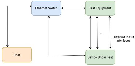
Host:
Host PC is a machine that is used to collect logs, generate log files, display on UI (User Interface), and allow the user to control the execution of the test. We have used the configuration of the host PC as given below:
- CPU - i7
- OS - Ubuntu 18.04 LTS
- Hard Drive - 500GB
- RAM - 16GB
Ethernet Switch:
Ethernet switch is used to provide a common medium of communication between the host, test equipment, and the Device Under Test (DUT). Each device is configured in such a way (with a range of IP addresses) that it is simple for them to communicate with one another.
Test Equipment:
Test equipment is used to test the external interfaces of the DUT. The test equipment has external interfaces identical to the DUT, where it links to the DUT via the external interfaces. In our case, we have used the test equipment to loop back data coming from the DUT.
Device Under Test:
Device Under Test is the STM32H7-based system that undergoes the DO-160 qualification testing. The DUT may have internal and external peripherals.
Internal peripherals are the ones that independently provide their output without communicating with the external hardware. For example, Temperature sensors, eMMC, and Norflash. External peripherals are the ones that provide their output while communicating with the external hardware. For example, UART, CAN (Controller Area Network), and RS-485.
Detail Framework Architecture
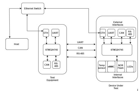
1. Device Under Test Software Components:
We have FreeRTOS with STM32 ecosystem packages (Hardware Abstraction Layer and other libraries). We have created a separate FreeRTOS task for each peripheral that is under test (including all external and internal peripherals). We have also created Logger and Control Mechanism tasks. Details about the FreeRTOS and FreeRTOS tasks can be found at: https://www.freertos.org/features.html.
The DUT software contains individual peripherals’ test tasks, logger tasks, and control mechanism tasks.
Below is the flow chart of the execution flow:
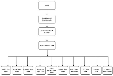
More tasks can be created based on the need and peripherals. Each task runs at 100ms periodicity. The table below shows the scheduling of each task till the sixth cycle. Each task is executed without affecting the other:
| Peripheral Name | Start Tick count | Interval | First Cycle | Second Cycle | Third Cycle | Fourth Cycle | Fifth Cycle | Sixth Cycle |
| UART | 1 | 100 | 1 | 101 | 201 | 301 | 401 | 501 |
| CAN | 10 | 100 | 10 | 110 | 210 | 310 | 410 | 510 |
| RS-485 | 20 | 100 | 20 | 120 | 220 | 320 | 420 | 520 |
| Ethernet | 30 | 100 | 30 | 130 | 230 | 330 | 430 | 530 |
| Temp sensor | 40 | 100 | 40 | 140 | 240 | 340 | 440 | 540 |
| eMMC | 50 | 100 | 50 | 150 | 250 | 350 | 450 | 550 |
| Nor Flash | 60 | 100 | 60 | 160 | 260 | 360 | 460 | 560 |
| LEDs | 70 | 100 | 70 | 170 | 270 | 370 | 470 | 570 |
| Logger | 80 | 100 | 80 | 180 | 280 | 380 | 480 | 580 |
| Control Task | 90 | 100 | 90 | 190 | 290 | 390 | 490 | 590 |
If the peripheral cycle is complete before time, FreeRTOS executes the idle task before the next task begins.
UART Test Task:
- UART interface connected between DUT - STM32 to the test equipment - STM32.
- DUT - STM32 transmits fix pattern data on the UART Tx channel at every 100ms of interval.
- DUT - STM32 receives data from the UART Rx channel.
- At DUT - STM32, the received data is compared with the transmitted data. If both match, it counts as PASS, else FAIL.
CAN Test Task:
- CAN interface connected between DUT - STM32 to the test equipment - STM32.
- DUT - STM32 transmits fix-pattern data to the test equipment over CAN at every 100ms of interval.
- After getting the data on the test equipment - STM32, it loops back the same message to DUT - STM32 over CAN.
- At DUT - STM32, the received message is compared with the transmitted data.
RS-485 Test Task:
- RS485 connected between DUT - STM32 to the test equipment - STM32.
- DUT - STM32 transmits fix-pattern data to the test equipment over the RS485 interface at every 100ms of interval.
- Test equipment receives data over RS485 and loops back the same data to DUT - STM32 over RS485 interface.
- At DUT - STM32, the received data is compared with the transmitted data.
Ethernet Test Task:
- Ethernet interface connected between DUT - STM32 to HOST PC.
- DUT - STM32 acts as a server with a 192.168.1.2 IP address and HOST acts as a client by configuring a 192.168.1.4 IP address.
- After the connection is established, the DUT - STM32 sends 1, 2, 3, 4, 5, 6, 7, 8 (characters) (fix data) to HOST over the Ethernet at every 100ms of interval.
- After the HOST gets the data, it loops back the same data to the DUT - STM32 over the Ethernet.
- At DUT - STM32, the received data is compared with the transmitted data.
Temperature Sensor Test Task:
- DUT - STM32 continuously reads and records the temperature from the temperature sensor at every 100ms of interval.
- Verifies that the temperature data is in range as mentioned in the datasheet (for ex: -55 to 125 Celsius)
eMMC Test Task:
- DUT - STM32 continuously performs the operation on eMMC Memory at every 100ms of interval.
- DUT - STM32 creates files in volume 1 partition.
- DUT - STM32 writes {0xA, 0x5, 0xA, 0x5, 0xA, 0x5, 0xA, 0x5, 0xA, 0x5, 0xA, 0x5, 0xA, 0x5, 0xA} 15 bytes of data in the file and closes that file.
- DUT - STM32 reads data from the file and compares it with the written data.
- DUT - STM32 deletes the file created from volume 1 partition.
Nor-Flash Test Task:
- DUT - STM32 continuously performs the operation on the QSPI-NOR Flash at every 100ms of interval.
- DUT - STM32 erases the sector.
- DUT - STM32 writes 256 bytes(A5A5) of data on the sector.
- DUT - STM32 reads 256 bytes of data from the sector.
- DUT - STM32 compares the data that it reads and writes.
LEDs Test Task:
- DUT - STM32 continuously toggles all on-board LEDs and reads their status at every 100ms of interval.
- Verifies the LED GPIO value.
Logger Task:
- This task gets the data from every interface (under test) and sends that log on the Ethernet interface (using the telnet protocol) that connects with the HOST.
Control Task:
- This task enables/disables the interface when requested by the HOST on the Ethernet interface.
2.Test Equipment Software Components:
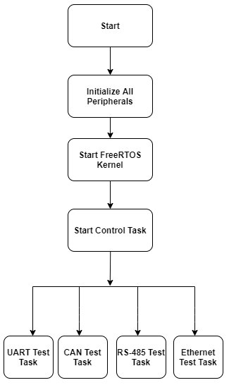
Test equipment software contains individual peripheral tasks to loop back values coming from the DUT.
Below is the flow chart of the execution flow:
| Peripheral Name | Start Tick count | Interval | First Cycle | Second Cycle | Third Cycle | Fourth Cycle | Fifth Cycle | Sixth Cycle |
| UART | 1 | 100 | 1 | 101 | 201 | 301 | 401 | 501 |
| CAN | 10 | 100 | 10 | 110 | 210 | 310 | 410 | 510 |
| RS-485 | 20 | 100 | 20 | 120 | 220 | 320 | 420 | 520 |
| Ethernet | 30 | 100 | 30 | 130 | 230 | 330 | 430 | 530 |
UART Test Task:
- Connected between the DUT and test equipment.
- The task receives data on the UART interface and sends it back on the UART interface (loopback data).
CAN Test Task:
- Connected between the DUT and test equipment.
- The task receives data on the CAN interface and sends it back on the UART interface (loopback data).
RS-485 Test Task:
- Connected between the DUT and test equipment.
- The task receives data on the RS-485 interface and sends it back on the UART interface (loopback data).
Ethernet Test Task:
- Connected between the DUT and test equipment.
- DUT acts as the server and the test equipment acts as the client.
- After the connection is built, the DUT task sends the data on the Ethernet interface.
- The test equipment receives data on the Ethernet interface sends it back to the DUT.
3.Host (GUI):
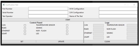
Graphical User Interface (GUI) provides control to the user for test-related information that appears in the logs, displays run-time logs with pass/fail status, and offers interface control.
The GUI interfaces with the DUT log and control interfaces via the Ethernet interface.
The image below shows a sample GUI that we have developed for testing purposes:
Here’s a sample log file:
Log files add logs for each cycle. Every cycle is of one minute and the count for each interface’s test shows how many times it gets tested in that one cycle.
This log file also contains details about the pass/fail status for each interface, along with information on the expected and actual results. The log file can be submitted as a part of the test result performed with the actual test result.
++++++++++++++++++++++++++++++++++++++++++++++++++++++++++++++++++++++++++++++++++
###################################### EUT #####################################
#
# PART NUMBER: XXXX
# HW CONFIGURATION: CCCC
# SW CONFIGURATION: YYYYYY
# MOD STATUS: YYYYY
# SERIAL NUMBER: 12345
# NAME OF THE TEST: Vibration Test
# TEST OPERATOR: ABC
#
################################# CYCLE COUNT :: 1 #################################
Interface Name: LED
Expected Value: GPIO_SET AND GPIO_RESET
Actual Value: GPIO_SET AND GPIO_RESET
Total Pass: 300
Total Fail: 0
LED - Test Result: Pass
--------------------------------------------------------------------------------
Interface Name: eMMC
Expected Value: 8
Actual Value: 8
Total Pass: 300
Total Fail: 0
eMMC - Test Result: Pass
--------------------------------------------------------------------------------
Interface Name: CAN
Expected Value: Msg Id:: 25, DATA :: 20 23 22 21 24
Actual Value: Msg Id :: 25, DATA :: 20 23 22 21 24
Total Pass: 300
Total Fail: 0
CAN - Test Result: Pass
--------------------------------------------------------------------------------
Interface Name: RS485
Expected Value: A 5 A 5 A
Actual Value: A 5 A 5 A
Total Pass: 300
Total Fail: 0
RS485 - Test Result: Pass
--------------------------------------------------------------------------------
Interface Name: Ethernet
Expected Value: 1 2 3 4 5 6 7 8
Actual Value: 1 2 3 4 5 6 7 8
Total Pass: 566
Total Fail: 0
Ethernet - Test Result: Pass
--------------------------------------------------------------------------------
Interface Name: UART
Expected Value: A 5 A 5 A
Actual Value: A 5 A 5 A
Total Pass: 300
Total Fail: 0
UART - Test Result: Pass
--------------------------------------------------------------------------------
Interface Name: Temperature Sensor
Expected Value: Between -55C to 125C
Actual Value: 31.375000
Total Pass: 300
Total Fail: 0
Temperature Sensor - Test Result: Pass
--------------------------------------------------------------------------------
Interface Name: NOR-FLASH
Expected Value: A5A5A5A5A5A5A5A5A5A5A5A5A5A5A5A5A5A5A5A5A5A5A5A5A5A5A5A5A5A5A5A5A5A5A5A5A5A5A5A5A5AActual Value: A5A5A5A5A5A5A5A5A5A5A5A5A5A5A5A5A5A5A5A5A5A5A5A5A5A5A5A5A5A5A5A5A5A5A5A5A5A5A5A5A5A5ATotal Pass: 300
Total Fail: 0
NOR-FLASH Test Result: Pass
--------------------------------------------------------------------------------
############################ SUMMARY FOR CYCLE COUNT: 1 ############################
#
# Total Interface Tested: 8
# Total PASS: 8
# Total FAIL: 0
#
############################ END FOR CYCLE COUNT: 1 ############################
++++++++++++++++++++++++++++++++++++++++++++++++++++++++++++++++++++++++++++++++++
The figure below depicts the flow chart of the GUI execution:
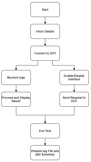
- In GUI, there is a control panel and a log status. The control panel provides control to the user to enable and disable the interface from the host and run time. The logs panel shows the results of each interface that is under test.
Conclusion:
While doing different tests (RF emission and susceptibility, Magnetic effect, Vibration, Temperature, and so on), the DUT will be in the test chamber connected with the test equipment and host via the Ethernet switch.
While the test is on and if any failure occurs in any of the interfaces, the qualification test engineer can easily check the pass/fail status on the GUI with its cycle count and time when the failure occurs. This architecture also provides the facility to the test engineer to enable/disable any interface while the test is in execution for debugging purposes to check whether that interface is causing the failure.
In a nutshell, this software architecture provides a complete granular approach of the software that makes the qualification test engineer’s life easier while doing the DO-160 qualification testing.
With in-depth knowledge and technical expertise in DO-254, DO-178B, DO-178C, DO-160 and ARP-4754 compliant Avionics systems. eInfochips is a one-stop solutions provider of critical avionics for commercial, business, military, and UAV programs. To know more about our aerospace offerings, please contact us today.
About the author
Darshan Talati
Darshan works as a Senior Technical Lead with eInfochips. He has more than 14 years of experience in embedded/aerospace product development and verification. He holds an M.Tech degree in software systems from BITS Pilani
